
Constructing Voltmeter Monitor Circuit using LM3914

The described circuit leverages the LM3914 integrated circuit, which is designed to drive LED displays in either bar or dot mode. In this application, it serves as a voltmeter to monitor voltage levels and signal when they fall outside predefined thresholds. The circuit operates at a supply voltage of 5V, making it suitable for various low-power applications.
The input voltage is fed into the LM3914, which compares it against a reference voltage set by a voltage divider composed of resistors. This reference voltage determines the thresholds for undervoltage and overvoltage conditions. When the monitored voltage exceeds the upper threshold, the LM3914 activates the corresponding LEDs to indicate an overvoltage condition. Conversely, if the voltage drops below the lower threshold, different LEDs will light up to signal an undervoltage condition.
Resistors in the circuit are crucial for setting the reference voltage and limiting current through the LEDs, ensuring they operate within safe parameters. The choice of resistor values will affect the sensitivity and accuracy of the voltage monitoring. Additionally, the circuit can be enhanced by including a microcontroller or additional logic gates to process the warning signals further, enabling integration into larger systems or triggering alarms.
Overall, this simple voltmeter monitor circuit is effective for real-time voltage monitoring and provides visual feedback through LED indicators, making it a valuable tool for various electronic applications.With a few resistors, LEDs and using a LM3914 bar/dot display driver IC we can construct a simple 5V Voltmeter Monitor Circuit which provides TTL-compatible undervoltage and overvoltage warning signals. A complete circuit can be shown in the schematic below 🔗 External reference
Related Circuits
This circuit is a conventional Pierce type oscillator that utilizes a JFET. It employs fundamental mode crystals and demonstrates good performance and reliability when a low noise JFET is used. The feedback is regulated by the capacitance C1, which...
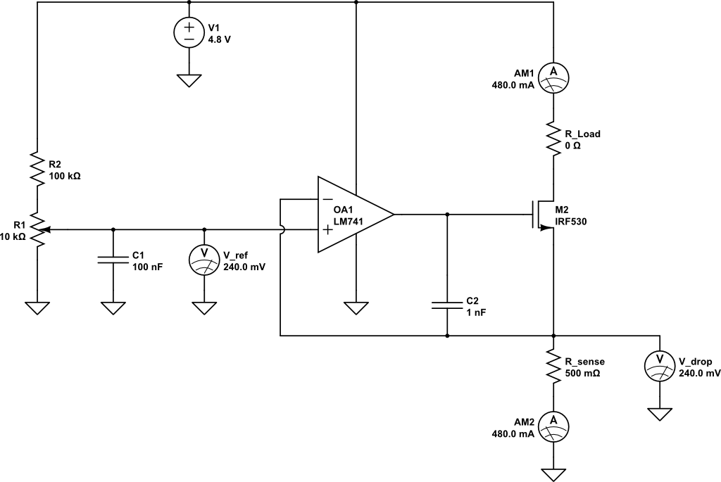
A current limiting circuit is designed to select a maximum current through a load, set to a maximum of 480 mA. As the load resistance increases, the series equivalent resistance (SER) of the limiting circuit decreases. When charging a...
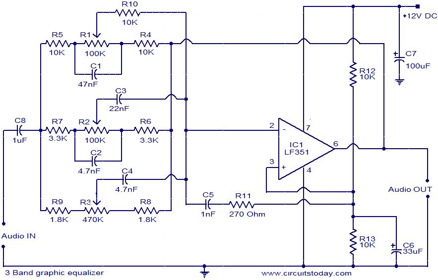
This document presents the circuit diagram of a simple three-band graphic equalizer that utilizes a single integrated circuit (IC) and a few additional components. The IC employed in this design is the LF351, which is a wide bandwidth single...
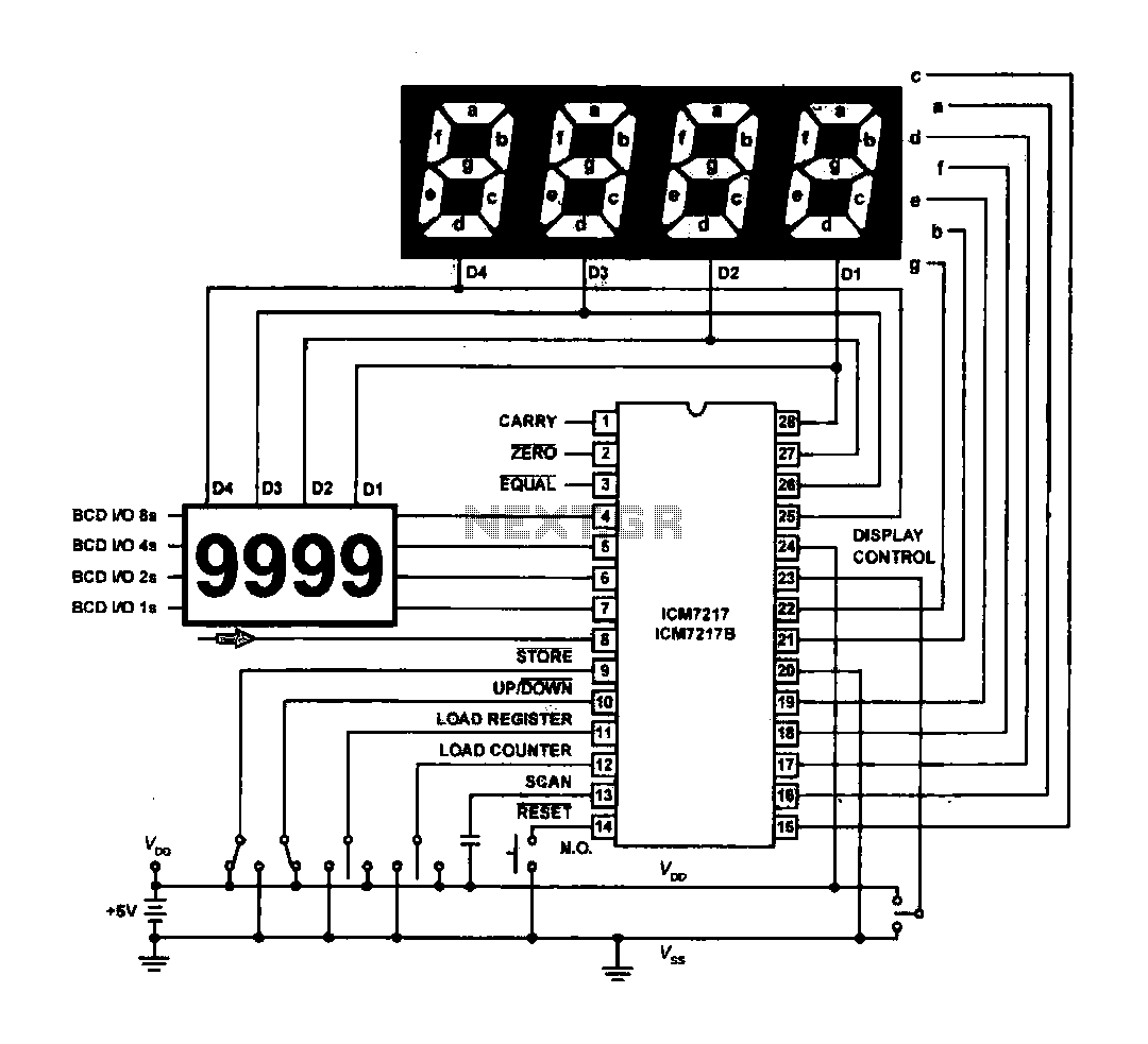
The circuit drives the light-emitting diode in a digital display configuration. The count signal is fed into the ICM7217 chip, which processes the count and subsequently drives the digital display board. The connection between the thumbwheel switches is illustrated...
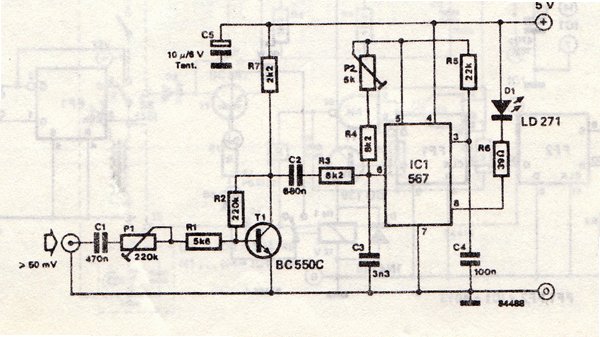
The transmitter is equipped with an LM567 tone decoder circuit. An audio signal (at least 50 mV peak-to-peak) is amplified with a transistor (T1) and then used to modulate IC1. The infrared transmitter frequency is adjusted with potentiometer P2...
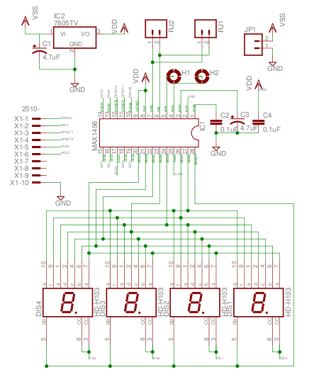
The MAX1496 is an analog-to-digital converter (ADC) that incorporates LED drivers, allowing for the construction of a 3 1/2 digit voltmeter using a minimal number of components. This device features both external and internal voltage reference options, along with...