
pierce xtal oscillator circuit

The Pierce oscillator configuration is widely recognized for its simplicity and effectiveness in generating stable oscillations. In this design, a Junction Field Effect Transistor (JFET) serves as the active device, providing the necessary gain and facilitating oscillation. The fundamental mode crystals utilized in this circuit are crucial for maintaining frequency stability, as they resonate at specific frequencies determined by their physical characteristics.
The feedback mechanism is established through capacitor C1, which connects the drain of the JFET to ground. This capacitor plays a vital role in determining the phase shift necessary for oscillation. The feedback ensures that a portion of the output signal is fed back to the input, reinforcing the oscillation process.
Frequency tuning is accomplished through the adjustment of shunt capacitance C2, which is placed in parallel with the crystal. By varying this capacitance, the effective load on the crystal changes, allowing for fine-tuning of the oscillation frequency. This feature is particularly advantageous in applications where multiple frequency outputs are required, as it enables easy switching between different crystals without the need for complex tuning mechanisms.
The parallel mode operation of the crystal allows for efficient energy transfer and helps to maintain the desired oscillation frequency. The circuit's design ensures that it can accommodate the switching of different crystals, making it versatile for various applications. Overall, this Pierce oscillator circuit represents a reliable solution for generating stable oscillations in electronic systems.This circuit is conventional Pierce type oscillator that uses a JFET. The circuit uses fundamental mode crystals. It has decent performance and reliability if we use a low noise JFET. This is the figure of the circuit. The feedback is controlled by the C1 Capacitance from drain to ground. Adjusting the frequency can be done by adjusting a shunt capacitance C2 across the crystal. The crystal works in parallel mode. This circuit is suitable where some crystals should be switched in and out to select the frequency, as there`s no tuning required. 🔗 External reference
Related Circuits
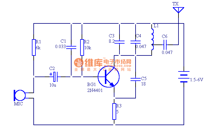
The circuit presented in this document utilizes 12 components to create a compact wireless FM microphone that operates with a stable frequency. The effective transmission range is approximately 30 meters, extending to over 100 meters when powered by a...

The circuit diagram illustrates an ultra-sensitive intruder alarm. The mere shadow of an intruder passing within a few meters of the circuit is sufficient to activate the alarm. In this setup, the IC2 uA741 is configured as a sensitive...
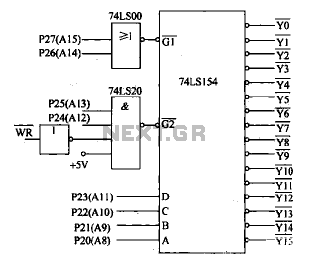
Decoding circuit: To ensure proper functionality of various interfaces, the system must assign IP addresses to all ports. Based on the number of system interfaces, it utilizes the 74LS154 decoder, which can translate up to 16 addresses. The interface...

This white LED floodlight illuminates your porch with cool white light. The circuit features a simple and energy-saving design, with a low current consumption. The LED floodlight circuit typically consists of a power supply, a control circuit, and the LED...

Two-Tone Siren Circuit Schematic Using One IC. This circuit is designed for children's entertainment and can be installed on bicycles, battery-powered cars, motorcycles, as well as models and various games and toys. It includes a switch (SW1) for operation. The...

This circuit is very similar to a Joule Thief, but it utilizes two transistors, does not include a transformer core, and employs only one inductor. The described circuit operates on principles akin to those of a Joule Thief, which is...
Warning: include(partials/cookie-banner.php): Failed to open stream: Permission denied in /var/www/html/nextgr/view-circuit.php on line 713
Warning: include(): Failed opening 'partials/cookie-banner.php' for inclusion (include_path='.:/usr/share/php') in /var/www/html/nextgr/view-circuit.php on line 713