
Corsair and Commando TXs
This document provides information about the Corsair and Commando Transmitters designed by Dave Martin of WNKR. It outlines the construction of each transmitter and includes examples created by others. The circuit diagram presented illustrates the initial two stages of a Corsair transmitter, noting that a low pass filter is not included in the output. It is recommended to incorporate one, as harmonics can be problematic even at low power levels. The transformer, AL21219, is sourced from a PYE Westminster W15AM PMR set and may be obtainable from "Garex." Alternatively, a custom transformer can be constructed using a small mains to 12V, 1A transformer. The original windings should be removed, and the primary should be wound with 80 turns of 24 SWG enamelled wire, connecting to pin 4 of the TDA2003. The secondary winding should consist of 180 turns of 22 SWG enamelled wire. An LM386 audio IC is employed for series modulation of Q2. The output on pin 5 of the LM386 is centered at half the supply voltage and modulated with the audio input. To handle higher currents, Q4 allows Q2 to draw more current without damaging the LM386. The power amplifier, Q3, is an IRF530 configured as a linear amplifier. To set up the circuit, adjust RV2 to achieve a DC voltage of 2.5 VDC at TP1, and then fine-tune the turns on L6 to obtain an RF output of 10 watts. It is crucial to use heatsinks for Q2, Q3, and Q4, and to mount Q3 and Q4 with a TO220 insulation kit.
The Corsair and Commando Transmitters are significant projects in the realm of amateur radio, showcasing unique design elements that emphasize performance and reliability. The absence of a low pass filter in the initial circuit design is a critical consideration for users. Harmonics can interfere with other frequencies, necessitating the addition of a suitable filter to mitigate potential issues.
The transformer selection is vital for ensuring optimal performance. The AL21219 transformer from the PYE Westminster W15AM PMR set is a recommended choice due to its compatibility and availability. For those opting to build a custom transformer, the specified winding instructions are essential to achieving the correct impedance and functionality. The winding specifications, including the wire gauge and number of turns, are designed to match the audio and RF characteristics required for effective modulation.
The use of the LM386 audio IC in the circuit serves a dual purpose: it provides audio modulation capabilities while ensuring that the output remains stable. The configuration allows for modulation without exceeding the IC's current limitations, thanks to the inclusion of Q4. This transistor acts as a current buffer, enabling the circuit to handle higher power levels without compromising the integrity of the audio signal.
The IRF530 power amplifier is a critical component in this design, serving as the final amplification stage. Proper setup and tuning are necessary to achieve the desired RF output power. The adjustments to RV2 and the turns on L6 are integral to optimizing the performance of the transmitter. The recommendation to use heatsinks for Q2, Q3, and Q4 is essential for thermal management, ensuring that these components operate within safe temperature limits during extended use. The use of a TO220 insulation kit for mounting Q3 and Q4 further enhances safety and reliability, preventing potential thermal issues and ensuring stable operation.
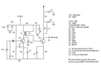
Overall, this circuit design exemplifies careful consideration of component selection, thermal management, and modulation techniques, all of which contribute to the successful operation of the Corsair and Commando Transmitters.All about the famous Corsair and Commando Transmitters designed by Dave Martin of WNKR. This blog will show you how to make each of the transmitters and show you examples that other people have made for them selves. The circuit below is basically the first 2 stages of a Corsair, it must be noted that there is no low pass filter on the output.
You s hould add one as even at these low powers harmonics can be a problem. A suitable filter will follow. The Transformer, AL21219 above, is from a PYE Westminister W15AM PMR set. It may be available from "Garex". As an alternative you may construct your own using a small transformer such as mains to 12v 1amp. Remove all the original winding and wind the primary with 80 turns of 24 SWG enamelled wire, this will be the audio side that connects to the TDA2003`s pin 4`s. The secondary winding is 180 turns of 22 SWG enamelled wire, A LM386 audio IC is used to series modulate Q2.
The LM386`s output on pin 5, sits at half the supply voltage. But is swung plus and minus with the audio being fed to it`s input. In the high current version Q4 allows Q2 to draw more current without damaging the LM386. The PA, Q3, is a IRF530 which is configured as a linear amplifier. To set up you should, by adjusting RV2, set the DC voltage at TP1 to 2. 5 VDC. Then by moving the turns on L6 further apart or closer together, get the RF power to read 10 Watts. It must be noted that Q2, Q3 & Q4 must have heatsinks and that Q3 & Q4 should be mounted using a TO220 insulation kit. 🔗 External reference
The Corsair and Commando Transmitters are significant projects in the realm of amateur radio, showcasing unique design elements that emphasize performance and reliability. The absence of a low pass filter in the initial circuit design is a critical consideration for users. Harmonics can interfere with other frequencies, necessitating the addition of a suitable filter to mitigate potential issues.
The transformer selection is vital for ensuring optimal performance. The AL21219 transformer from the PYE Westminster W15AM PMR set is a recommended choice due to its compatibility and availability. For those opting to build a custom transformer, the specified winding instructions are essential to achieving the correct impedance and functionality. The winding specifications, including the wire gauge and number of turns, are designed to match the audio and RF characteristics required for effective modulation.
The use of the LM386 audio IC in the circuit serves a dual purpose: it provides audio modulation capabilities while ensuring that the output remains stable. The configuration allows for modulation without exceeding the IC's current limitations, thanks to the inclusion of Q4. This transistor acts as a current buffer, enabling the circuit to handle higher power levels without compromising the integrity of the audio signal.
The IRF530 power amplifier is a critical component in this design, serving as the final amplification stage. Proper setup and tuning are necessary to achieve the desired RF output power. The adjustments to RV2 and the turns on L6 are integral to optimizing the performance of the transmitter. The recommendation to use heatsinks for Q2, Q3, and Q4 is essential for thermal management, ensuring that these components operate within safe temperature limits during extended use. The use of a TO220 insulation kit for mounting Q3 and Q4 further enhances safety and reliability, preventing potential thermal issues and ensuring stable operation.
Overall, this circuit design exemplifies careful consideration of component selection, thermal management, and modulation techniques, all of which contribute to the successful operation of the Corsair and Commando Transmitters.All about the famous Corsair and Commando Transmitters designed by Dave Martin of WNKR. This blog will show you how to make each of the transmitters and show you examples that other people have made for them selves. The circuit below is basically the first 2 stages of a Corsair, it must be noted that there is no low pass filter on the output.
You s hould add one as even at these low powers harmonics can be a problem. A suitable filter will follow. The Transformer, AL21219 above, is from a PYE Westminister W15AM PMR set. It may be available from "Garex". As an alternative you may construct your own using a small transformer such as mains to 12v 1amp. Remove all the original winding and wind the primary with 80 turns of 24 SWG enamelled wire, this will be the audio side that connects to the TDA2003`s pin 4`s. The secondary winding is 180 turns of 22 SWG enamelled wire, A LM386 audio IC is used to series modulate Q2.
The LM386`s output on pin 5, sits at half the supply voltage. But is swung plus and minus with the audio being fed to it`s input. In the high current version Q4 allows Q2 to draw more current without damaging the LM386. The PA, Q3, is a IRF530 which is configured as a linear amplifier. To set up you should, by adjusting RV2, set the DC voltage at TP1 to 2. 5 VDC. Then by moving the turns on L6 further apart or closer together, get the RF power to read 10 Watts. It must be noted that Q2, Q3 & Q4 must have heatsinks and that Q3 & Q4 should be mounted using a TO220 insulation kit. 🔗 External reference
Related Circuits
The digital readout of the Corsair 560 is positioned above the tuning knob. In this radio, the six-digit display often fluctuated, frequently doubling the frequency indication. The reading was unstable, making it challenging to determine the tuned frequency. After...