
countdown timer circuit

The Countdown Timer Circuit is designed to count down from a specified time interval and visually display the remaining time on a seven-segment display. The circuit typically includes a microcontroller or a timer IC, such as the 555 timer, which is configured in a monostable or astable mode, depending on the desired functionality. The timer can be set to trigger at specific intervals determined by external resistors and capacitors, allowing for precise time management.
In addition to the timer IC, the circuit incorporates a seven-segment decoder, such as the CD4511 or 74HC4511, which converts binary-coded decimal (BCD) inputs from the microcontroller into the corresponding outputs for the seven-segment display. This enables the visual representation of the countdown process. The display is usually driven by transistors or a dedicated driver IC to ensure adequate current supply for the segments.
The user interface may include buttons for setting the countdown time and starting or stopping the timer. A reset function is often included to allow the user to return to the initial state. Power supply considerations are crucial, as the circuit may require a stable voltage source, typically 5V or 9V, depending on the components used.
Overall, the Countdown Timer Circuit serves as an educational project that demonstrates the principles of digital electronics, including timing functions, binary counting, and display technologies, while providing practical insights into circuit design and implementation.Countdown Timer Circuit is a project submitted by my group, namely, M. Amit, P. Briones, R. Enriquez, R. Lacson, A. Saldivar (yours truly), K. Tom, and A. Uy, for our ECE 130 - Computer Application class way back August 31, 2006 at University of St. La Salle, Philippines. INTRODUCTION The seven-segment decoder is used in.. 🔗 External reference
Related Circuits
Most homes today have at least a few infrared remote controls, whether for the television, video recorder, stereo, or other devices. Despite this, many individuals have experienced frustration when a light remains on after settling into a comfortable chair...
Probably the easiest way of doing automatic switch off is with relay logic. In the diagram, the box marked RL1 is the coil, the 2 in the coil box tells you there are two sets of contacts somewhere on...
An inverter is introduced which primarily utilizes a MOS field-effect transistor in conjunction with a conventional power transformer. The output power of the inverter is determined by the specifications of both the MOS field-effect transistor and the transformer, thereby...
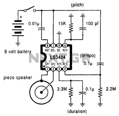
A high-quality melody circuit produces a slow decay waveform that generates chime-like notes. The pitch, tempo, and duration of the notes are all adjustable. The melody circuit is designed to offer a versatile sound generation capability, making it suitable for various...
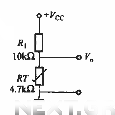
The basic application circuit for thermistors is illustrated. Figure (a) depicts a fundamental temperature measurement circuit. The accuracy of this temperature measurement is not high and is suitable only for applications with lower precision requirements. RT represents a positive...

When the system is placed in a shop or mall, logos and product advertisements serve as an ideal complement to temperature information. For home use, photographs of children at the beach or, should the temperature drop, images of making...