
Counter display with led 7 segment by IC CMOS
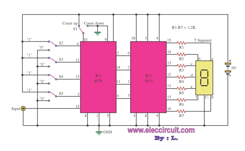
The digital counter circuit is designed using the 4029 binary counter integrated circuit, which counts in binary and can be configured to count up or down based on external control signals. The 4029 features a parallel load capability, allowing it to be preset with a specific value, making it versatile for various counting applications.
The output from the 4029 is fed into the 4513 integrated circuit, which serves as a BCD to 7-segment decoder/driver. The 4513 translates the binary coded decimal (BCD) output from the counter into the appropriate signals needed to illuminate the segments of a 7-segment display. The 7-segment display consists of seven individual LEDs arranged in a figure-eight pattern, which can represent numeric digits from 0 to 9.
In terms of circuit connections, the 4029’s output pins are connected to the input pins of the 4513, ensuring that the binary data is correctly interpreted. Control pins on the 4513, such as the enable and blanking inputs, can be utilized to manage the display output effectively, allowing for features like turning off the display or enabling it based on specific conditions.
Power supply connections for both ICs must be ensured, typically using a regulated +5V source. Proper decoupling capacitors should be placed near the power pins of both ICs to filter out noise and ensure stable operation.
Overall, this digital counter circuit can be applied in various applications such as timers, clocks, and scoreboards, providing a clear visual representation of the counted values through the 7-segment display.This is the simple digital counter circuit, the IC application number 4029 from binary data, and then sent to the IC number 4513, a driver IC 7 Segment, to show. 🔗 External reference
Related Circuits
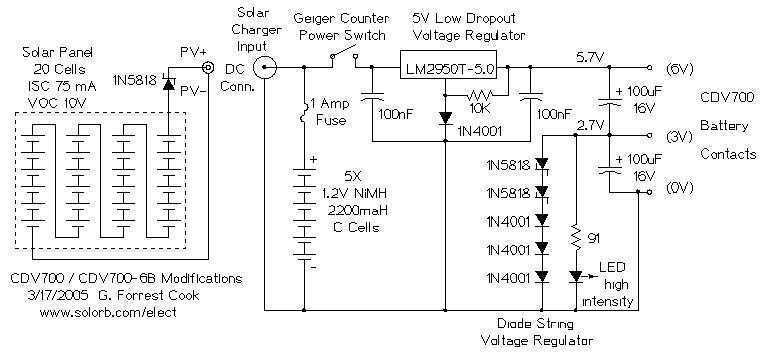
This project involves making several modifications to an early 1960s era Victoreen CDV700 or CDV600-6B geiger counter. These counters are available on E-Bay for around $50 to $100. The modifications use modern electronic parts to improve the counter's stability,...
This is a simple flashing LED circuit featuring two LEDs and two NPN transistors. It demonstrates the behavior of transistors and capacitors, and it can be used in an oscillating configuration. The circuit consists of two NPN transistors, which function...
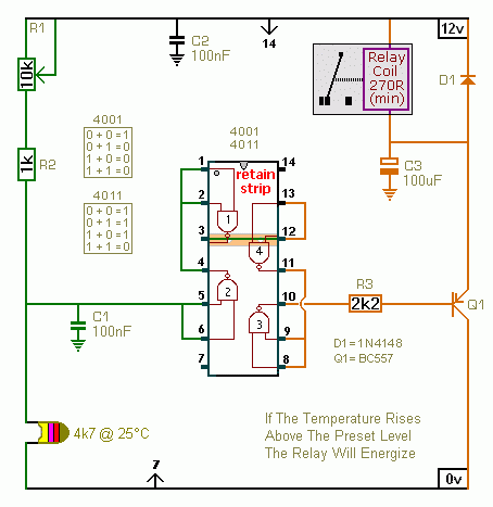
A CMOS 4001 or a CMOS 4011 can be utilized in this circuit, as both contain four two-input gates. The inputs of each gate are connected together, allowing them to function as simple inverters. This means that when both...

Function generators are essential in the design, testing, and operation of encoders, modulators, demodulators, and measurement instruments. This document presents an economical method to construct a bus-controlled sinewave oscillator that exhibits exceptionally low distortion. The circuit produces a sinusoidal...
This electronic clock comprises the LM8365 and the LDD640R displays. The LM8365 can show the hour/minute and month/day. Users can set two alarm outputs, AD1 and AD2, by pressing either the 12h or 24h button. The operating voltage range...
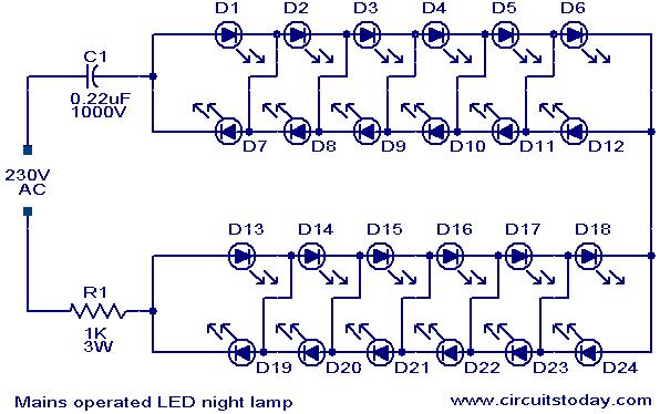
This is a simple and effective LED-based night lamp circuit that can be powered directly from a 230V mains supply. The circuit uses a total of 24 white LEDs and produces an output of approximately 15W. The resistor R1...
Warning: include(partials/cookie-banner.php): Failed to open stream: Permission denied in /var/www/html/nextgr/view-circuit.php on line 713
Warning: include(): Failed opening 'partials/cookie-banner.php' for inclusion (include_path='.:/usr/share/php') in /var/www/html/nextgr/view-circuit.php on line 713