
µP-Controlled Oscillator Delivers Rock-Bottom Distortion

The described circuit provides a robust solution for generating low-distortion sinewave outputs suitable for a variety of applications in electronic design and testing. The use of a dual-filter building block allows for precise frequency control, while the tracking notch filter ensures that unwanted harmonics do not affect the output quality. The buffer amplifier serves to isolate the oscillator from subsequent stages, maintaining signal integrity. The integration of a bus-controlled clock generator allows for flexible interfacing with microcontrollers or other digital systems, facilitating easy integration into larger electronic systems. The option to modify the circuit for quadrature outputs enhances its versatility, making it suitable for applications such as phase modulation and signal processing. Overall, this bus-controlled sinewave oscillator design exemplifies a cost-effective approach to generating high-quality sinusoidal signals with minimal distortion.Function generators often play a critical role in the design, testing, and operation of encoders, modulators, demodulators, and measurement instruments. Here`s an inexpensive way to build a bus-controlled sinewave oscillator that has downright low distortion.
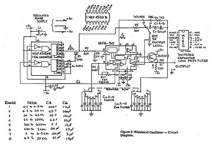
The circuit generates a sinusoidal output with typical second and third harmonics down fr om the fundamental by -76. 1 and -74. 2 dB, respectively, across its full output range of 10 Hz to 10 kHz. That performance represents better than a 40-dB improvement over common diode-shaped sinewave generators, which employ a diode-shaping technique to transform a square wave into a sinewave. Typically, their second-and third-order harmonics are down from the fundamental by -35 and -25. 5 dB, respectively. The circuit consists of four sections ( see the figure ). At the heart of the design, the first one is the oscillator comprising an IC dual-filter building block (U1), a second-order clocked filter (whose bandpass-filter section sets the oscillator`s frequency), and a comparator (U2A).
The bandpass filter determines the oscillator`s frequency by allowing signals only around its center frequency to pass. Equation 1 shows the oscillator frequency, and Equation 2 the filter The second circuit section is the tracking notch filter, which is set to and tracks the oscillator`s third harmonic, which is the higher-amplitude harmonic.
The tracking filter is synchronously clocked with the oscillator`s frequency-setting filter to provide lock-step oscillator-tracking filter-response characteristics. The third section has a buffer amplifier (U3A) with a gain of -1. This section includes a 13. 3-kHz low-pass filter to reduce the high-frequency component generated by the clocking steps in the output waveform.
The fourth section is a bus-controlled clock generator that mainly comprises an IC serial-port programmable oscillator (U4), which can be either the LTC6903 for the serial peripheral interface (SPI) or the LTC6904 for the Inter-IC (I2C) interface. Some pull-up resistors, a decoupling capacitor, and a resistor in series with the output are the only external components required.
Plus, the circuit can be modified easily to produce a quadrature, sine/cosine-waveform output. Just add a second output op amp and take its input from the bandpass output of U1 (BPB at pin 11). 🔗 External reference
Related Circuits
The simplest method of detecting metal is through a beat frequency oscillator. The circuit consists of two balanced oscillators: one serves as the detector element while the other provides a reference signal. The reference oscillator frequency is set to...
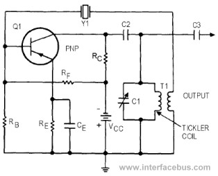
This circuit represents a variant of an Armstrong Oscillator. This specific example incorporates a crystal along with the LC tank circuit utilized in the previous Series-Fed Armstrong Oscillator. By definition, the Armstrong Oscillator employs a tickler coil for feedback...
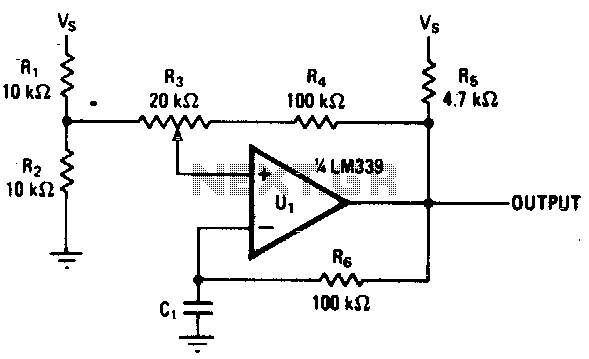
Varying the amount of hysteresis in this comparator circuit allows for smooth adjustment of output frequencies within the range of 740 Hz to 2 kHz. The hysteresis level, in combination with the time constant formed by resistor R6 and...
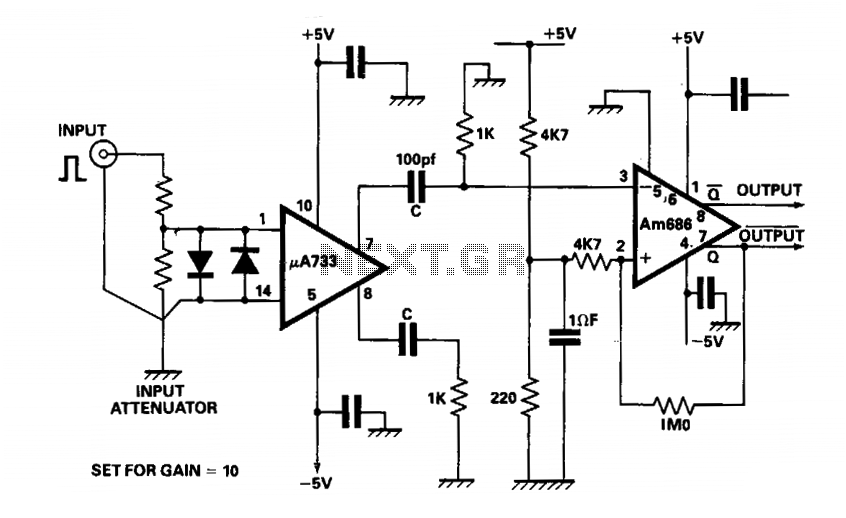
The output of a video amplifier is differentiated before being fed to a Schottky comparator. The propagation delay is typically reduced to 10 ns. The output pulse width is determined by the value of C, 10 pF, resulting in...
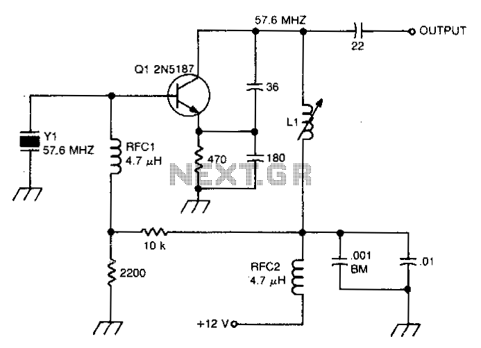
This circuit isolates the crystal from the DC base supply using an RF choke for improved starting characteristics. The circuit design features an RF choke that serves as a crucial component for isolating the crystal oscillator from the DC base...
A low distortion audio frequency sine wave can be generated by passing the output of a simple square wave oscillator through a sharp cutoff low-pass filter to attenuate the odd harmonic components. The output level of the sine wave...
Warning: include(partials/cookie-banner.php): Failed to open stream: Permission denied in /var/www/html/nextgr/view-circuit.php on line 713
Warning: include(): Failed opening 'partials/cookie-banner.php' for inclusion (include_path='.:/usr/share/php') in /var/www/html/nextgr/view-circuit.php on line 713