
CRT final video driver amplifier
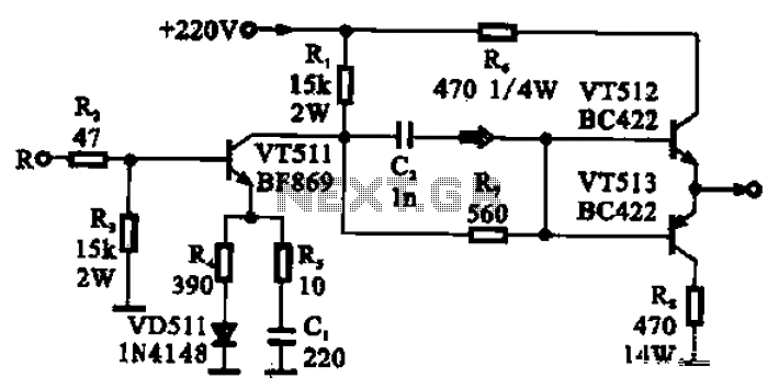
The CRT final video driver amplifier is designed to efficiently drive the cathode of a cathode-ray tube (CRT) by employing a complementary push-pull configuration. The circuit's core consists of three transistors: VT511, VT512, and VT513. VT511 serves as the driver amplifier, configured as a common emitter amplifier. This configuration is notable for its high voltage gain, which is essential for amplifying the input video signal.
The input signal is received from the polar group and is routed through resistor R2. This resistor plays a critical role in ensuring that the base current to VT511 does not exceed safe limits, thereby protecting the transistor from potential damage due to excessive current. The amplified signal that emerges from the collector of VT511 is then directed to the complementary push-pull stage comprised of VT512 and VT513.
In this push-pull configuration, VT512 operates as an NPN transistor, while VT513 functions as a PNP transistor. This arrangement allows for efficient amplification of both halves of the input waveform, which is crucial for maintaining signal integrity in video applications. The output stage is effectively two emitter followers, which serve to buffer the output and provide a low output impedance. The circuit is biased at 20V, which is optimal for achieving the desired output characteristics.
The low output impedance is particularly important as it allows the amplifier to drive the kinescope cathode effectively, ensuring that the CRT can produce a bright and clear image. The high output amplitude characteristics of the amplifier are also critical, as they ensure that the signal delivered to the cathode is sufficient to produce the necessary electron beam intensity for image rendering. Overall, this configuration is optimized for high-performance video applications, delivering both reliability and efficiency in driving CRT displays. CRT final video driver amplifier FIG complementary push-pull final video driver amplifier, which is composed of three transistors, VT511 as a driver amplifier, which uses a com mon emitter amplifier having a high gain in the form of t characteristics, R signal input from the polar group, enter resistor R2 has the effect of limiting, to prevent excessive base current - the amplified signal output from the collector, and then sent to a complementary push-pull amplifier VT512, VT513 base, VT512 of NPN transistor, VT513 PNP type transistor, then complementary push-pull output stage, the equivalent of two emitter follower, biased by a 20V provides a low output impedance, high output amplitude characteristics of having to provide a drive signal to kinescope cathode.
Related Circuits
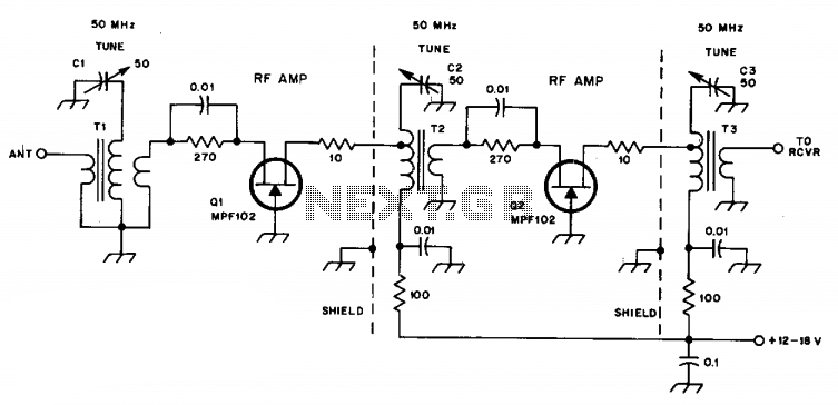
C1, C2, and C3 are miniature ceramic or plastic trimmers. T1 (main winding) has an inductance of 0.34 µH, utilizing 11 turns of No. 24 enameled wire wound on a T37-10 toroid core. The antenna winding consists of one...
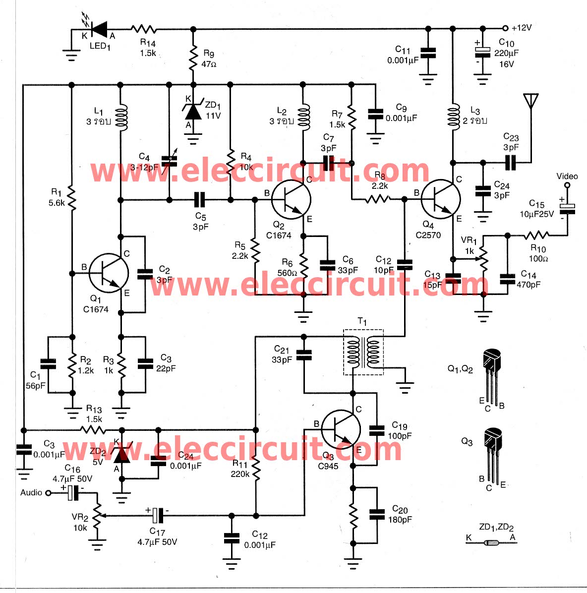
To transmit video and audio signals to multiple televisions simultaneously, a video amplifier splitter utilizing a transistor can be employed. A video amplifier splitter is an electronic device designed to distribute a single video and audio signal to multiple output...
The standard Class AB audio power amplifier allows for direct coupling of the amplifier's output to speakers. This is beneficial as it eliminates capacitors or transformers that could compromise sound quality. The speakers are connected directly to the amplifying...
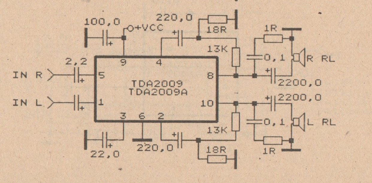
The minimum voltage required for this circuit is 8 volts, while the maximum voltage is 28 volts. It can be used to amplify audio signals in electronic devices such as radios, DVDs, MP4 players, and MP5 players. The circuit...
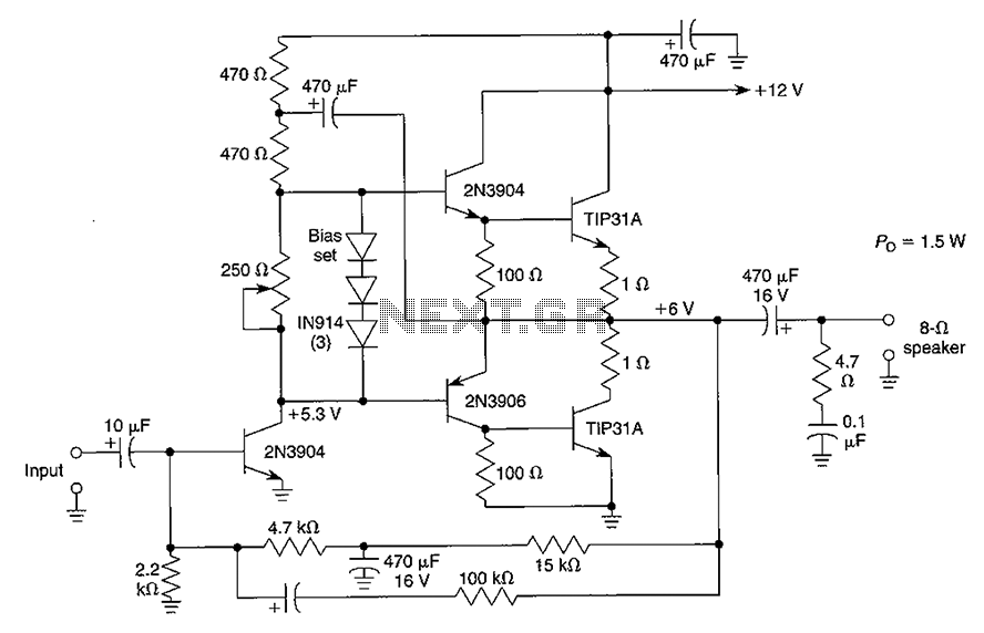
Although the integrated circuit (IC) has largely replaced this circuit, the flexibility of the discrete device design still makes it practical. The components are readily available and cannot easily be eliminated. If desired, a small piece of metal can...
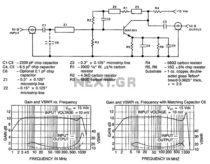
This circuit design is a Class A amplifier that utilizes both AC and DC feedback. The bias is stabilized at 15 mA of the collector current through the use of DC feedback from the collector. The AC feedback, which...