
A DC Fault Protection Circuit for Audio Amplifiers
The Class AB audio power amplifier is characterized by its ability to deliver high-quality audio output while minimizing distortion. The direct coupling method enhances fidelity by ensuring that the audio signal passes through fewer components, thereby preserving the integrity of the sound. However, the risk of connecting raw DC to speakers in the event of a failure necessitates the integration of robust protection mechanisms.
Protection circuits can be designed to detect anomalies in the output signal and disconnect the speakers before damage occurs. Simple fuses can provide a basic level of protection but may not react quickly enough to transient events. More sophisticated designs incorporate monitoring circuits that can detect overcurrent conditions and activate protective measures swiftly.
The use of MOSFETs as switches in speaker protection circuits leverages their fast switching capabilities and low on-state resistance. This makes them ideal for high-fidelity audio applications where any distortion can be detrimental. The configuration of two MOSFETs in a source-to-source arrangement allows for effective bidirectional control of AC signals, addressing the limitations of single MOSFETs.
Photovoltaic MOSFET drivers represent a significant advancement in controlling these switches. By converting light into electrical energy, these drivers eliminate the need for complex control circuitry and provide a reliable means to operate MOSFETs in audio applications. The design must ensure that the gate voltages are appropriately managed to prevent unintended conduction, particularly in AC applications.
Overall, the integration of advanced MOSFET technology and innovative protection circuits in Class AB amplifiers enhances their performance and reliability, ensuring that high-quality audio reproduction is maintained while safeguarding speakers from potential damage.The standard Class AB audio power amplifier allows for direct coupling of the output of the amplifier to speakers. This is very good in that no capacitors or transformers get in the way of the sound quality coming out.
The speakers are connected directly (more or less!) to the amplifying devices. This has the unfortunate side effect that if an out put device fails, this usually causes the raw DC power supply to be connected to the speakers. Most speakers burn out or are mechanically damaged by this very quickly. Protection circuits have been designed to prevent this kind of damage, and come in many flavors. They range from the simple - such as an added fuse in series with the amplifier output - to the complex, with all sorts of monitoring. The current favorite is a series relay circuit at the output of the amplifier, driven by some sort of DC detection circuit.
Relays have their own set of problems, though, not the least of which is reliability. Relay contacts corrode, arc and stick over time. Worse, each time they are tested could well be the last time they operate, so there are some built in problems. Fuses are also problematical, as they must be excruciatingly well sized to offer good protection, and when that is done, the fuse resistance is modulated by the heat dissipated in the fuse near maximum power, so there are audible side effects.
Some recent advances in power MOSFETs make them attractive for replacing or sidestepping relays and fuses on the output of the power amp. Power MOSFETs make good switches, changing from a totally nonconductive state to a fractional-ohm resistor in nanoseconds with the proper drive signal.
Unlike bipolar transistors, there is no offset voltage or rectification associated with a MOSFET`s on-state conduction. As long as the current through the MOSFET is low enough to not cause a significant voltage drop across the MOSFET during current peaks, the MOSFET itself will not be audible.
There are some difficulties with driving MOSFETs as AC relays, though. There is an inherent substrate diode in all MOSFETs that looks to the outside world like a diode connected across the source-to-drain. This diode conducts freely in the reverse direction. This can actually help protect the MOSFET in some situations, but it means that a single MOSFET can`t block current in both directions.
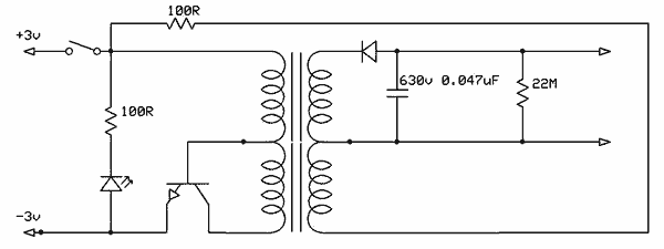
However, putting two MOSFETs source-to-source can. The substrate diodes then are alternately reverse biased on either signal polarity. Suitable enhancement of gate-to-source voltage then gives us a bidirectional AC switch. The sources are always riding on the instantaneous signal level, though, and both gates must be made about 10-12V more positive than that moving signal level. This is very difficult to do for most floating drive circuits. International Rectifier has released several photovoltaic MOSFET drivers. These units comprise an LED to produce light, and several photovoltaic diodes in series. When the LED shines on the photodiodes, they produce a voltage on the output pins of the unit. In the direct replacement for an output relay, two N-channel power MOSFETs are connected source-to-source and gate-to-gate.
The drain terminals are used as the input and output of a switch. When the gate-source terminals of the two MOSFETs have 0V between them, the devices are off, and no current can flow, up to the breakdown voltage of the MOSFETs. When the gates of the MOSFETs are several volts positive with respect to the sources, both MOSFETs are enhanced, and current can flow.
Modern MOSFETs can have a resistance from drain to source in the milliohm region. The photovoltaic isolator makes for a simple, easy, way to turn the two units on or off because the voltage-source side of the isolator rides along with the source terminals while the LED side may be tied to any level necessary for operation. To turn the "relay" on, just force current through the LED. To turn it off, j 🔗 External reference
Related Circuits
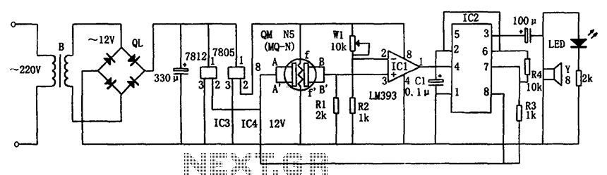
The circuit consists of a buck rectifier and voltage regulator, a gas sensor, a comparator circuit, and an alarm sound circuit. The buck regulator circuit includes a transformer, a bridge rectifier, and components such as QL, IC3 (7812), and...
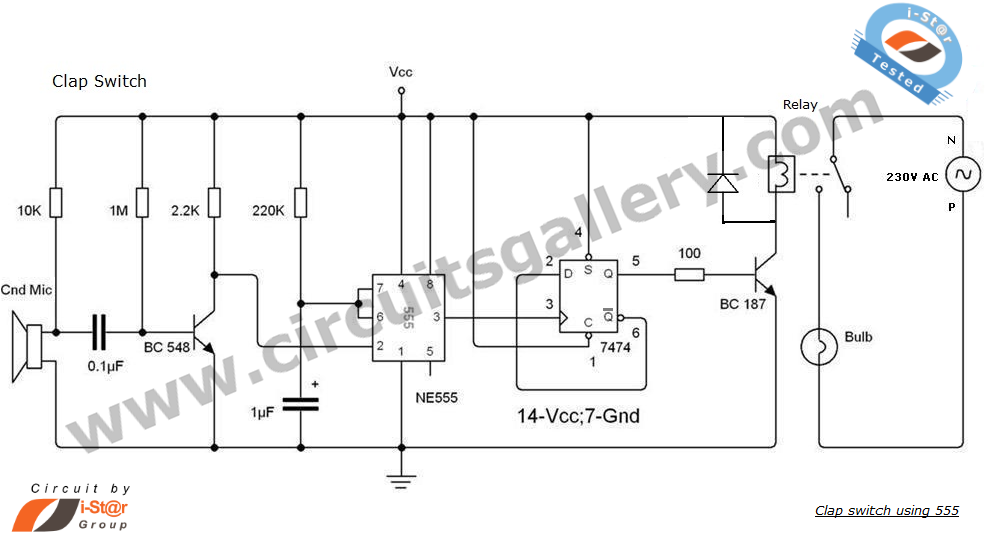
This is an intriguing 555 timer circuit designed to entertain and engage individuals while studying electronics in educational settings. Commonly referred to as a clap switch circuit, it operates as a sound-controlled flip-flop. This sound-controlled light can also function...
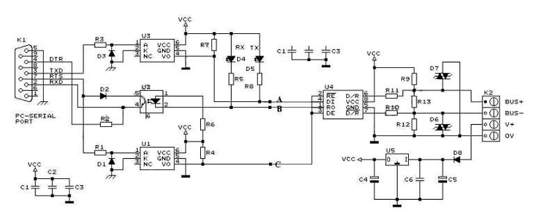
RS232 to RS485 Converter Circuit Schematic. RS232 to RS485 converters are primarily utilized in industrial and commercial settings. The RS232 to RS485 converter circuit is designed to facilitate communication between devices using different serial communication standards. RS232 is commonly found...
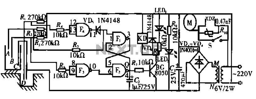
The circuit operates by monitoring the water level in a tank. When the water level falls below a specified point (F), the RS flip-flop (F2) is activated, producing a high Q output that energizes a relay to start the...
An FM transmitter, commonly referred to as an FM transmitter, utilizes two transistors, specifically the 2N2222 model. When in operation, this FM transmitter requires a 9-volt battery for power and operates with an antenna that is less than 12...
Free energy motors and generators are available for purchase, featuring plans for overunity devices. These devices resemble oscillators used in Joule thief circuits, although there may be some errors present in the designs. However, the concept remains clear. Free energy...
Warning: include(partials/cookie-banner.php): Failed to open stream: Permission denied in /var/www/html/nextgr/view-circuit.php on line 713
Warning: include(): Failed opening 'partials/cookie-banner.php' for inclusion (include_path='.:/usr/share/php') in /var/www/html/nextgr/view-circuit.php on line 713