
Crystal Oscillator
The crystal oscillator's circuit design is pivotal in achieving frequency stability and performance. The crystal is typically connected in a configuration that allows it to operate in its series-resonant mode, where the impedance is minimized, enhancing the feedback loop's effectiveness. The feedback path is crucial, as it determines the oscillator's gain and stability. The resistors in the biasing network must be carefully selected to ensure that the DC operating point remains stable, preventing drift that could lead to frequency instability.
In addition to the feedback network, careful consideration must be given to the layout of the PCB to minimize parasitic capacitance and inductance, which could affect the oscillator's performance. Shielding may also be necessary to protect the oscillator from external electromagnetic interference, which could influence its frequency stability.
The choice of crystal is also critical; factors such as the cut type (e.g., AT-cut or BT-cut), frequency tolerance, and temperature coefficient need to be evaluated to ensure optimal performance in the intended application. The characteristics of the crystal and the surrounding circuitry ultimately determine the oscillator's ability to maintain a precise frequency over varying environmental conditions.
In summary, the design and implementation of a crystal oscillator require a comprehensive understanding of both the crystal's physical properties and the electrical characteristics of the surrounding circuit. This knowledge is essential for developing reliable and stable oscillators for various electronic applications.In crystal oscillators, the usual electrical resonant circuit is replaced by a mechanically vi brating crystal. The crystal (usually quartz) has a high degree of stability in holding con stant at whatever frequency the crystal is originally cut to operate.
The crystal oscillators are, therefore, used whenever great stability is needed, for examp le, in communication trans mitters, and receivers, digital clocks etc. A quartz crystal exhibits a very important property known as piezo-electric effect. Whena mechanical pressure is applied across the faces of the crystal, a voltage proportional tothe applied mechanical pressure appears across thecrystal. Conversely, when a voltage is applied across the crystal surfaces, the crystal is distorted by an amount proportional to the applied voltage.
An alter nating voltage applied to a crystal causes it to vibrate at its natural frequency. Besides quartz, the other substances that exhibit the piezo-electric effect are Rochelle salt and tourmaline. Rochelle salt exhibits the greatest piezoelectric effect, but its applications are limited to manufacture of microphones, headsets and loudspeakers.
It is because the Rochelle salt is mechanically the weakest and strongly affected by moisture and heat. Tourmaline is most rugged but shows the least piezo-electric effect. Quartz is a compromise between the piezoelectric effect of Rochelle salt and the mechani cal strength of tourmaline.
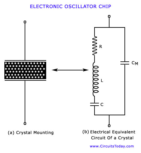
It is inexpensive and readily available in nature. It is mainly the quartz crystal that is used in radio-frequency (RF) oscillators. For use in electronic oscillators, the crystal is suitably cut and then mounted between two metal plates, as shown in fig (a). Although the crystal has electro-mechanical resonance but the crystal action can be represented by an electrical resonance circuit, as shown in fig.
(b). The crystal actually behaves as a series R-L-C circuit in parallel with CM where CM is the capacitance of the mounting electrodes. Because the crystal losses, represented by R, are small the equivalent crystal Q is high-typically 20, 000.
Values of Q upto 106 can be obtained by making use of crystals. Because of presence of CM, the crystal has two resonant fre quencies. One of these is the series resonant frequency fs at which2 fL = 1/2 fCand in this case the crystal impedance is verylow. The other is parallel resonance frequency fp which is dueto parallel resonance of capacitance CM and the reactance of the series circuit.
In this case crystal impedance is very high. The impedance versus frequency curve of the crystal is shown in figure. In order to use the crystal properly it must be connected in a circuit so that its low impedance in the series-resonant op erating mode or high impedance in the anti-resonant or paral lel resonant operating mode is selected. Two resonant frequencies are given by the expressionsSeries resonant frequency, fs = 1/2 LC Parallel resonant frequency, FP = 1/2 [1 + C/CM] / LC It appears that fp is higher than fs but the two frequencies are very close to each other.
It is due to the fact that the ratio C/CM is very small. To stabilize the frequency of an oscillator, a crystal may be operated at either its series or parallel resonant frequency. To excite a crystal for operation in the series-resonant mode it may be connected as a series element in a feedback path, as shown in figure.
In this mode of operation the crystal impedance is the smallest and the amount of positive feedback is the largest. Resistor R1, R2 and RE provide a voltage-divider stabilized dc bias circuit, the capacitor CE provides ac bypass of the emitter resistor R and the radio-frequency coil (RFC) provides for dc bias -while decoupling any ac signal on the power lines from affecting the output signal.
The voltage feedback sigrTal from the collector to the base is maximum when the crystal impedance i 🔗 External reference
Related Circuits
Incandescent lamp has been used to reduce harmonic distortion in sine oscillator circuit. The nonlinear resistance characteristic of the lamp filament help the circuit to shape the signal to approximate the ideal sine wave. Here is the classic Wien-bridge...
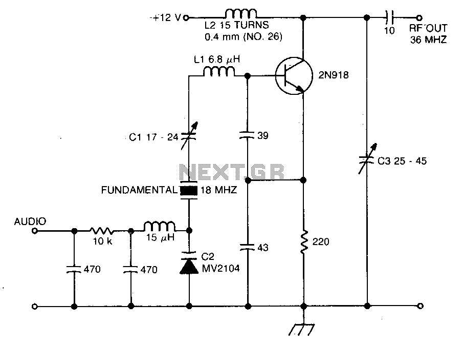
The crystal operates into a complex load at series resonance. L1, C1, and C2 balance the crystal at zero reactance. Capacitor C1 fine-tunes the center frequency. A tank circuit consisting of L2 and C3 doubles the output frequency, allowing...
Achieving the appropriate amplifier loop gain is a significant challenge in generating a low distortion, constant amplitude sine wave. Nevertheless, this issue can be addressed with... Amplifier loop gain is a critical parameter in the design of audio and signal...
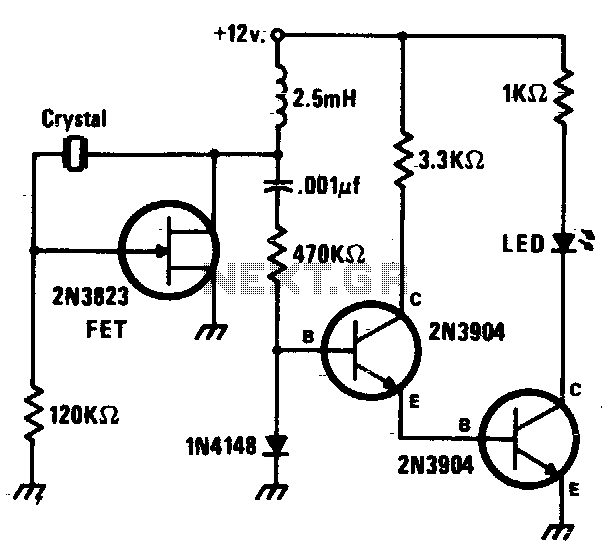
This circuit is a simple Pierce oscillator with an LED go/no-go display. The checker works best with crystals having fundamental frequencies in the seven to eight megahertz range. The Pierce oscillator circuit is a popular choice for generating high-frequency signals,...
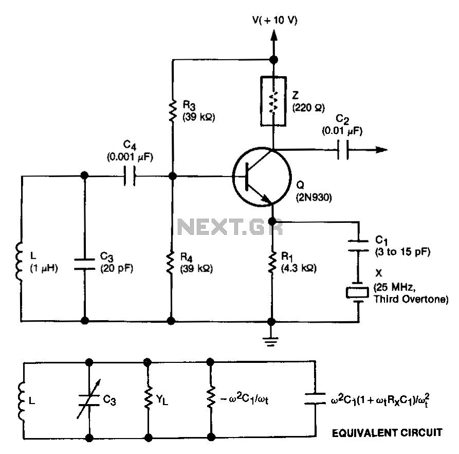
This unit is easily tunable and stable, consumes minimal power, and is more cost-effective than other types of oscillators that operate at similar frequencies. This unique combination of features is made possible by a design concept that involves operating...

The Hartley Oscillator is an LC oscillator that derives its feedback from magnetically coupled energy in a tapped coil. Hartley oscillators are inductively coupled variable frequency oscillators. The Hartley Oscillator is a type of electronic oscillator that utilizes an inductor-capacitor...