
Hartley oscillator

The Hartley Oscillator is a type of electronic oscillator that utilizes an inductor-capacitor (LC) circuit to generate oscillations. It is characterized by its use of two inductors and one capacitor, which form a resonant circuit. The feedback mechanism is achieved through a tapped coil, allowing for variable frequency operation.
In a typical Hartley oscillator circuit, the two inductors are often connected in series, and one of them is tapped to provide feedback to the amplifier stage. This feedback is crucial for maintaining oscillations, as it ensures that the output signal is amplified and fed back into the circuit in phase with the input signal. The frequency of oscillation is primarily determined by the values of the inductors and the capacitor, following the formula:
\[ f = \frac{1}{2\pi\sqrt{L_{total}C}} \]
where \( L_{total} \) is the equivalent inductance of the two inductors. The configuration allows for easy tuning of the oscillation frequency by adjusting the tap point or changing the values of the inductors or the capacitor.
The Hartley oscillator is commonly used in radio frequency applications, signal generators, and other electronic devices where stable oscillations are required. Its ability to produce a sine wave output makes it suitable for various applications, including modulation and demodulation in communication systems. The design can be implemented using discrete components or integrated circuits, depending on the required specifications and performance criteria.
Overall, the Hartley oscillator is valued for its simplicity, reliability, and ease of frequency adjustment, making it a popular choice in oscillator design.The Hartley Oscillator is an L C oscillator that derives its feedback from magnetically coupled energy in a tapped coil. Hartley oscillator are inductively coupled variable frequency oscillators. 🔗 External reference
Related Circuits
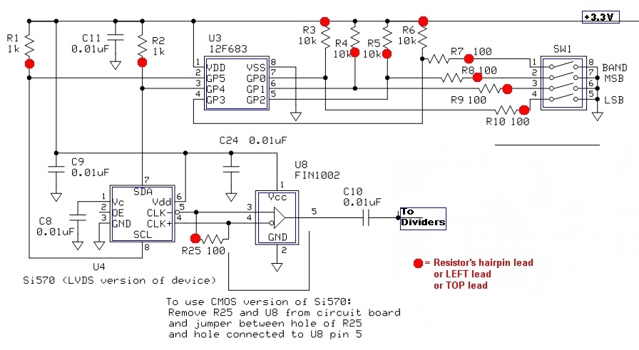
The current draw should be between 80 and 100 mA. The exact value is highly dependent on the Si570, its version (CMOS vs. LVDS), the frequency setting, and variations in the circuit components. The SW1 programming of U3 can...
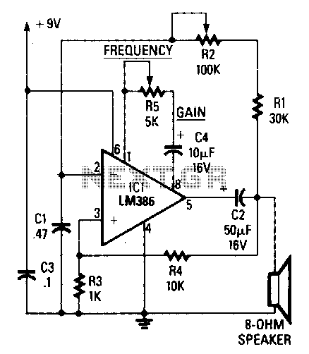
The circuit's frequency of oscillation is given by the formula: f = 2.8 / [C1 x (R1 + R2)]. By adjusting the potentiometer R2, the output frequency can be varied from 60 Hz to 20 kHz. A portion of...
The circuit consists of two oscillators, both working at about 465 kHz. One uses an if transformer and the other uses an inductor (the search coil LI). The oscillators are coupled by a capacitor (10 pF). A beat note...
The schematic diagram presented is of a twin "T" phase shift oscillator, an audio oscillator. This oscillator derives its name from the phase shift network formed by resistors R3, R4, and capacitors C1, C2, and C3. This network shifts...
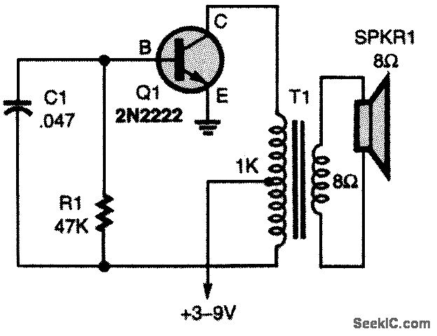
The oscillator circuit employs a center-tapped transistor output transformer that functions as a load for the collector of Q1, provides a feedback signal to the base, and acts as the output winding to drive the speaker. Resistor R1 supplies...
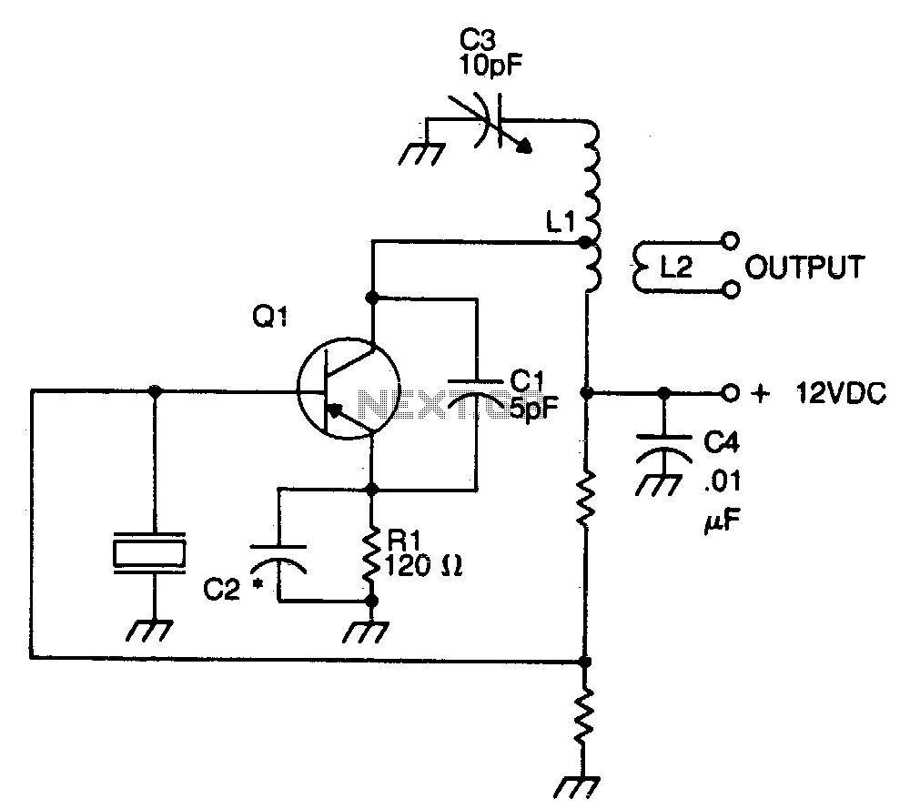
The crystal element in this circuit is connected directly between the base and ground. Capacitor C1 is utilized to enhance feedback due to the internal capacitances of the transistor. This capacitor should be positioned as close as possible to...