
Crystal Oscillator Circuit
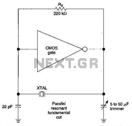
The described circuit utilizes a CMOS amplifier configured to operate within its linear region, facilitated by the biasing resistor RB. This configuration is essential for ensuring that the amplifier can effectively amplify signals without distortion. The pi-type crystal network comprises two capacitors (C1 and C2) and a crystal oscillator (XTAL), which collectively create a feedback loop that is critical for generating oscillations.
At the resonant frequency, the pi network achieves a 180-degree phase shift. This phase shift is a crucial requirement for sustaining oscillations, as it ensures that the output of the amplifier is in phase opposition to the input, thereby reinforcing the oscillatory behavior. The interaction between the capacitive elements and the crystal oscillator determines the frequency stability and the quality of the oscillation produced.
The design and selection of components within this circuit are vital. The values of capacitors C1 and C2 must be chosen to ensure that the resonant frequency aligns with the desired operating frequency of the oscillator. Additionally, the characteristics of the crystal (XTAL) should match the circuit requirements to provide accurate frequency control and stability.
In summary, this CMOS amplifier circuit exemplifies a classic oscillator design, leveraging the properties of a pi-type network to achieve the necessary phase shift for oscillation, while the biasing provided by resistor RB ensures optimal performance in the linear operating region of the amplifier. The CMOS amplifier is biased into the linear region by resistor RB. The pi-type crystal network (CI and C2, and XTAL) provides the 180 phase shift at the resonant frequency which causes the circuit to oscillate. 🔗 External reference
Related Circuits
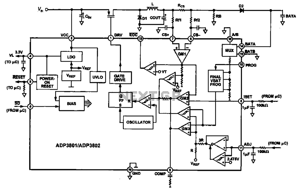
Charging circuit diagram for personal work based on the operating principle of ADP3801/3802 charging circuit. The ADP3801/3802 is a highly integrated battery charger controller designed for Li-ion and Li-polymer batteries. The charging circuit typically consists of several key components including...

This is a simple passive headphone distribution box that functions effectively. It has been utilized in various recording studios and constructed for multiple users. The absence of active components ensures minimal failure risk and a quick assembly process. The...
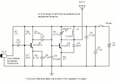
The following circuit illustrates a Wireless Car Alarm Circuit Schematic Diagram. Features include the ability to detect sounds within a 20-meter radius, a 1/16 wavelength antenna, and the capability to transmit radio signals up to 2 kilometers. Q1 serves...
This device is a simple timer that keeps the headlights of a vehicle on for approximately 1 minute and 30 seconds, allowing access to dark areas without the need to manually switch off the lights. Activating switch P1 initiates...
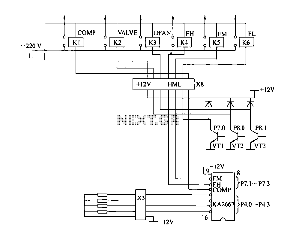
The driving circuit depicted in Figure 18-12 consists of a connection between the driving portion, the microcontroller, and the air conditioning operation components of the bridge. The microcontroller's digital signal levels from ports P4.0 to P4.3 (approximately 12 feet)...
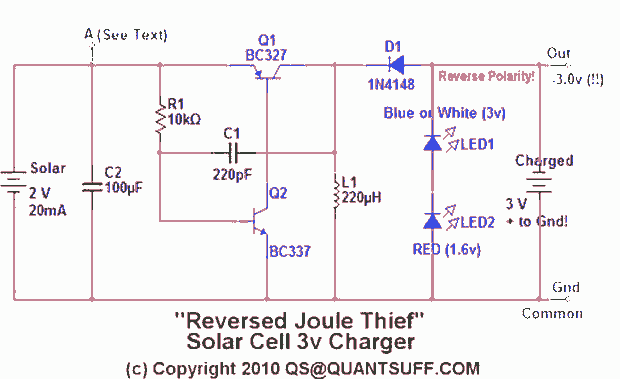
This design presents an innovative approach to the Joule Thief (JT) circuit typically utilized in garden lights. Instead of directly charging a 1.2V battery from the solar cell and converting the power to operate a 3-volt LED, this circuit...
Warning: include(partials/cookie-banner.php): Failed to open stream: Permission denied in /var/www/html/nextgr/view-circuit.php on line 713
Warning: include(): Failed opening 'partials/cookie-banner.php' for inclusion (include_path='.:/usr/share/php') in /var/www/html/nextgr/view-circuit.php on line 713