
Car Headlights Timer Circuit
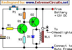
The circuit operates by utilizing a basic timer mechanism that relies on a capacitor and resistor to create a delay. When switch P1 is pressed, capacitor C1 begins charging. The charging current flows through R1, allowing C1 to accumulate voltage until it reaches the supply voltage level. Once fully charged, Q1 is activated, allowing current to flow through Q2, which energizes the relay RL1. The relay contacts close, completing the circuit to the headlights and keeping them illuminated.
The timing characteristics of the circuit are dependent on the RC time constant, which is calculated as τ = R1 × C1. The precise timing can be adjusted by varying the resistance of R1 or the capacitance of C1. For example, increasing R1 will lengthen the time it takes for C1 to charge, resulting in a longer delay before the headlights turn off. Conversely, increasing C1 will also extend the timing, but care must be taken to select a capacitor with a suitable voltage rating and tolerance.
In the variation where the interior lamp is used as a command source, the diode configuration ensures that C1 can only discharge when the door is closed, providing a more automated lighting solution. This is particularly useful for scenarios where manual operation may be inconvenient. The diode prevents backflow of current, ensuring that the charging and discharging processes are properly isolated.
Overall, this timer circuit provides a practical solution for maintaining headlight illumination in low-light conditions while incorporating flexibility for different operational modes. The design is simple yet effective, making it suitable for various automotive applications.This device is a simple timer, allowing to keep on the headlights of your vehicle for about 1min. and 30sec. , e. g. when accessing some dark place, without the necessity of coming back to switch-off the lights. Pushing on P1 allows C1 charging to full 12V battery supply. Therefore Q1 is driven hard-on, driving in turn Q2 and its Relay load. The hea dlights are thus activated by means of the Relay contact wired in parallel to the vehicle`s headlights switch. RL1 remains activated until C1 is almost fully discharged, i. e. When its voltage falls below about 0. 7V. The timing delay of the circuit depends by C1 and R1 values and was set to about 1min. and 30sec. In practice, due to electrolytic capacitors wide tolerance value, this delay will vary from about 1min.
and 30sec. to 1min. and 50sec. An interesting variation is to use the inside lamp as a command source for the timer. In this way, when the door is opened C1 is charged, but it will start to discharge only when the door will be closed, substituting pushbutton operation. To enable the circuit acting in this way, simply connect the cathode of a 1N4002 diode to R1-C1 junction and the anode to the "live" lead of the inside lamp.
This lead can be singled-out using a voltmeter, as it is the lead where a 12V voltage can be measured in respect to the vehicle frame when the lamp is on. 🔗 External reference
Related Circuits
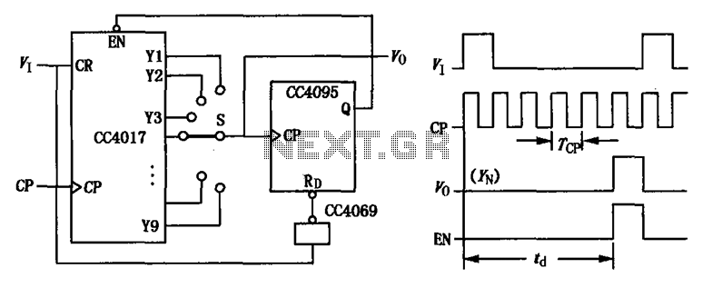
CC4017 counter/distributor featuring a circuit diagram of the delay. The CC4017 is a decade counter and distributor that counts from 0 to 10, providing ten output states. It is commonly used in various digital applications for counting purposes, such as...
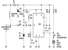
The sections available in this datasheet cover general design considerations for the 555 timer, frequently asked application questions (FAQ), design formulas, and examples of innovative applications. Examples of applications include a Missing Pulse Detector, Pulse Width Modulation (PWM), Tone...
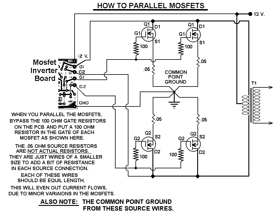
This 1000-watt power inverter circuit diagram is based on the MOSFET RF50N06. For increased power output, additional MOSFETs can be paralleled with the RF50N06. These MOSFETs are rated for 60 volts and 50 amps. It is essential to connect...
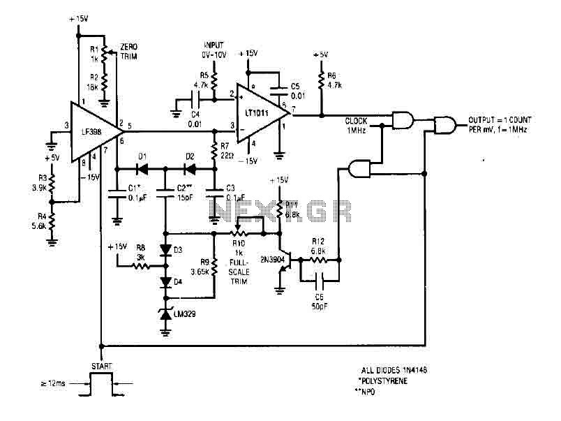
The simple 4-digit converter circuit has an output count of 1, designed for a frequency range from f-IMHz to 10.000 MHz. All diodes used in the circuit are IN4146 "POLYSTYRENE" NPO. The circuit utilizes the LF398 at the input...
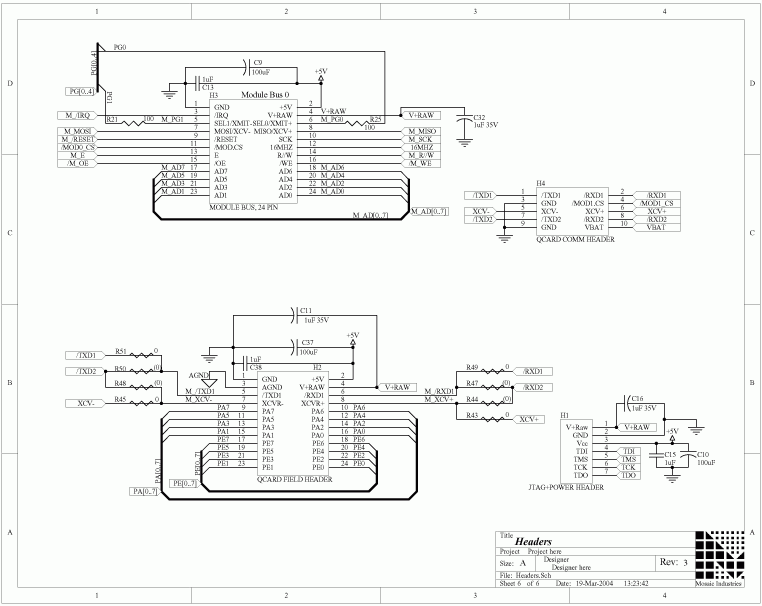
The QCard Controller Single Board Computer (SBC) features the Freescale 68HC11 microcontroller, along with RAM and Flash memory, digital input-output (I/O), and analog-to-digital (A/D) conversion capabilities. For comprehensive details regarding the QCard headers mentioned on this page, refer to...
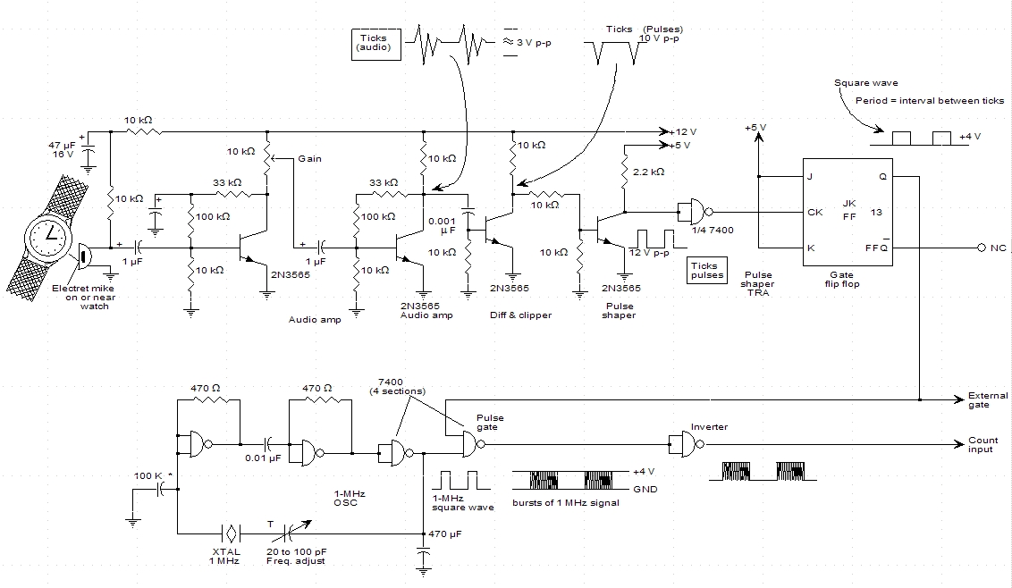
A schematic for a watch timer was found in a hobby electronics book. The circuit adapts a frequency counter to measure intervals. Watch ticks are clipped, shaped, and formed into a square wave. This square wave is utilized to...