
Current Booster

The described circuit utilizes a linear voltage regulator, such as the LM708 or LM317, to maintain a stable output voltage while managing current requirements. These regulators have a defined current limit, typically around 1.5 A for the LM317. When the load demands exceed this limit, the circuit incorporates a power transistor, such as the 2N3772, to provide additional current.
In operation, the voltage regulator handles the primary regulation of voltage and current up to its specified limit. When the load requires more than this limit, the regulator begins to conduct more heavily, effectively allowing the power transistor to take over the excess current demand. The transistor operates in parallel with the regulator, with its base connected to the output of the regulator. This configuration ensures that the transistor turns on when the load exceeds the regulator’s capacity, thereby allowing it to supply the additional current needed.
To achieve higher current outputs, multiple power transistors can be stacked in parallel. This arrangement allows for the distribution of current across several devices, reducing the thermal load on each transistor and enhancing the overall power handling capability of the circuit. Care must be taken to ensure that each transistor shares the load evenly, which may necessitate the use of small resistors in series with each transistor's emitter to balance the current.
Thermal management is crucial in this design, as both the voltage regulator and the power transistor will generate heat during operation. Adequate heatsinks must be utilized to dissipate this heat efficiently, preventing thermal overload and ensuring reliable operation. The size and thermal characteristics of the heatsinks should be chosen based on the maximum expected load current and the ambient operating temperature.
In summary, this circuit effectively extends the current handling capability of linear voltage regulators by utilizing power transistors to share the load, while careful attention to thermal management ensures reliable operation under varying load conditions.Volt regulators such as the LM708, and LM317 series (and others) sometimes need to provide a little bit more current then they actually can handle. If that is the case, this little circuit can help out. A power transistor such as the 2N3772 or similar can be used (See the project on the 3-part variable power supply).
The power transistor is used to boost the extra needed current above the maximum allowable current provided via the regulator. Current up to 1500mA(1.5amp) will flow through the regulator, anything above that makes the regulator conduct and adding the extra needed current to the output load.
It is no problem stacking power transistors for even more current. (see diagram). Both regulator and power transistor must be mounted on an adequate heatsink. 🔗 External reference
Related Circuits
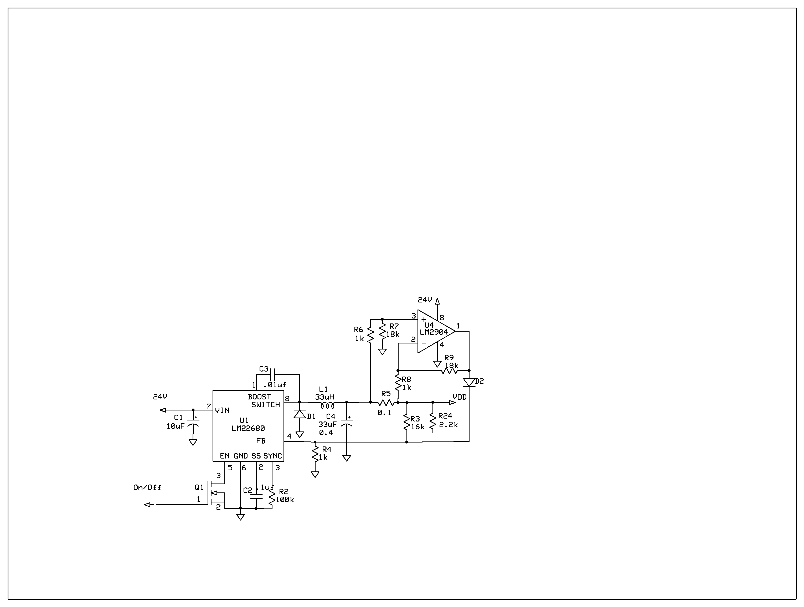
The product requires a voltage-controlled, current-limited power supply. Various switcher chips have been used with an op-amp to provide feedback for a current sense voltage to the feedback pin. Currently, an LM22680 is in use, but it has shown...
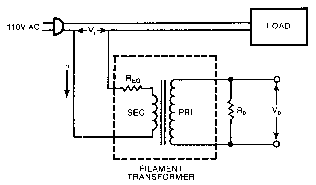
A low-cost filament transformer provides a linear indication of the load current in an AC line. This method causes a slight series voltage drop over a wide range of load currents. A low-cost filament transformer is utilized in applications requiring...
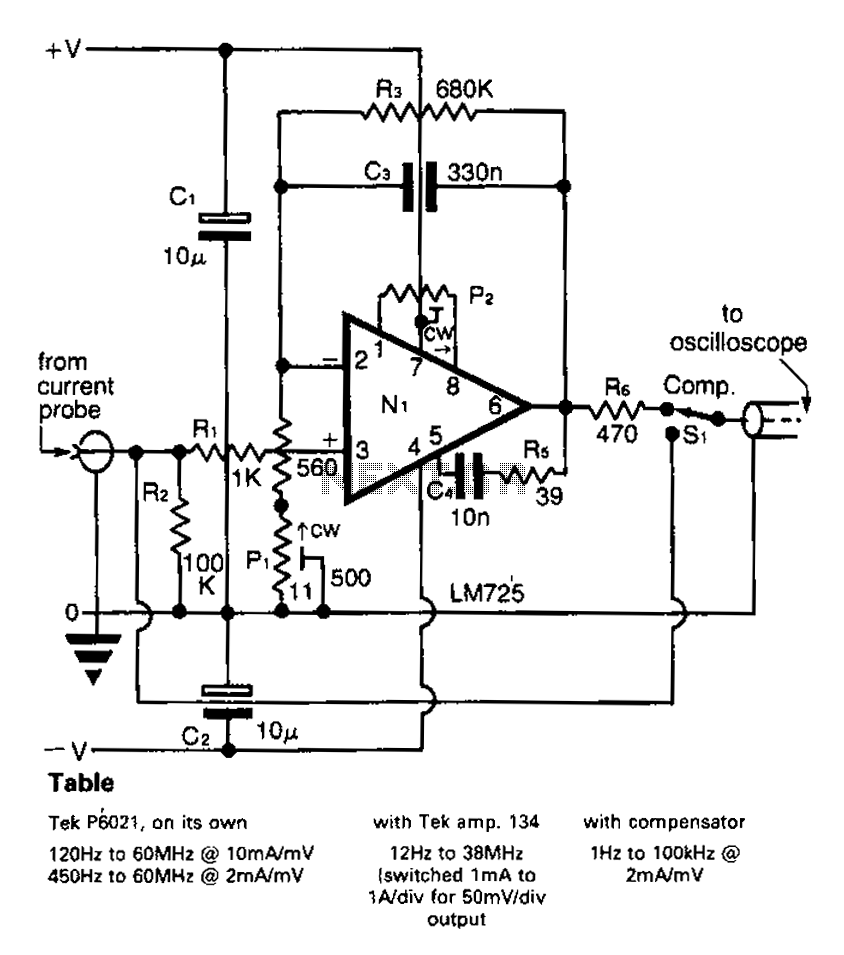
A clip-on current probe, like the Tektronix P6021, is a valuable tool for displaying current waveforms on an oscilloscope. However, it has limitations in low-frequency response. Specifically, the P6021 is sensitive to a range of 2mA/mV, and frequencies below...
Switch on one unit, and everything else you need turns on automatically. This can save the tedium of turning on half a dozen different things, when one should be enough! This is another project created purely from necessity. In...
Afshin Izadian at Indiana University has developed a new power inverter that utilizes a single switching transistor and is capable of generating infinite-level voltages. The power inverter designed by Afshin Izadian represents a significant advancement in the field of power...
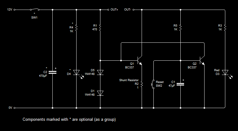
This entry describes a modification of a current limiter circuit originally created by Ron J. The original circuit functions as intended; however, a need arose to disconnect the load immediately after the maximum current threshold was reached, effectively creating...