
Current Sensing Slave Power Switch
The described project involves the creation of a master control switch that enables the simultaneous activation of multiple devices, such as computer peripherals and audio equipment, through a single action. The schematic for this project typically incorporates a relay or a series of relays that are activated by the main power switch of the primary device—such as a PC or audio system.
The relay serves as an electrically operated switch that can control the power to multiple outlets. The circuit design may include a low-voltage control circuit that is triggered when the primary device is turned on. This control circuit can be designed using a microcontroller or simple transistor switching, depending on the complexity required.
In a basic setup, a normally open (NO) relay is connected in parallel with the power switch of the primary device. When the primary device is powered on, the relay closes, allowing current to flow to the other connected devices. Additional features may include LED indicators to show the status of each device, fuses for overload protection, and possibly a delay circuit to prevent inrush current when multiple devices are powered simultaneously.
To enhance functionality, the design can incorporate a timer or programmable logic to sequence the power-up of devices, which can be particularly useful for audio equipment to prevent pops or clicks during startup. The inclusion of surge protection components, such as MOVs (Metal Oxide Varistors), can further safeguard the connected devices from voltage spikes.
Overall, this circuit aims to streamline the power management of multiple devices, providing both convenience and reliability in everyday use.Switch on one unit, and everything else you need turns on automatically. This can save the tedium of turning on half a dozen different things, when one should be enough! This is another project created purely from necessity. In my case, it was to switch on all my computer peripherals when the PC was turned on, but I shall be building another very shortly to do the same with my Hi-Fi equipment. 🔗 External reference
Related Circuits

This is the design of a bias current compensation circuit. This circuit can operate with medium wattage source resistances while maintaining a minimal increase in the equivalent offset voltage. It is based on the LM11 operational amplifier. The circuit...
Power diagram videos for a DIY solar panel system wiring diagram. This is an exact diagram of the power window wiring diagram available in printed books on Amazon, covering power door locks and wiring diagrams. The provided description outlines a...
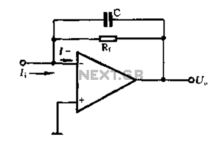
A current-voltage conversion circuit. A current-voltage conversion circuit is designed to transform an input current signal into a corresponding voltage signal. This type of circuit is fundamental in various applications, including sensor interfacing, signal conditioning, and analog-to-digital conversion processes. Typically,...
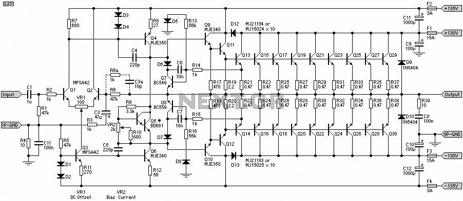
A 1500W power amplifier circuit design diagram created by Rod Elliott. The circuit utilizes 10 pairs of power transistors, specifically MJ15024 and MJ15025, or alternatively MJ21193 and MJ21194. The 1500W power amplifier circuit is designed for high-performance audio applications, providing...
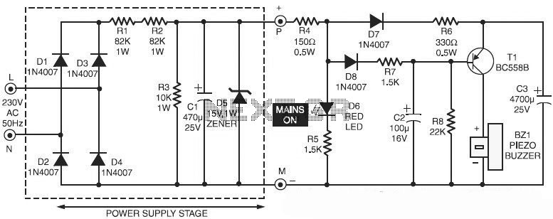
This is a specialized circuit design for a power supply failure alarm. Most power supply failure alarm or indicator circuits require an independent power supply. However, the alarm circuit presented here... The power supply failure alarm circuit is designed to...
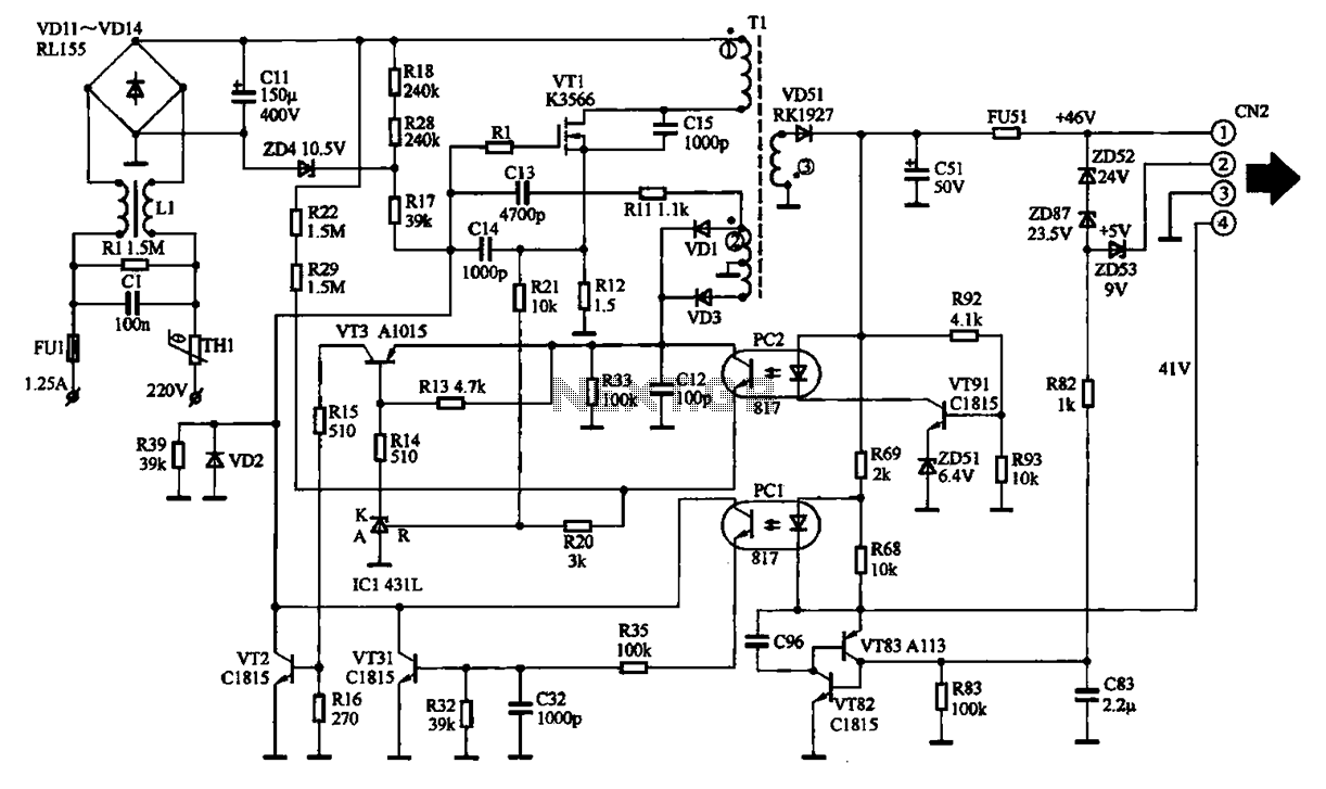
The EPSON PHOTO 830U printer power circuit illustrates the power supply circuit for the EPSON PHOTO 830U printer, which operates as a switching power supply. During normal operation, the power supply input socket receives a 220V AC supply to...