
current simple h-bridge polarity reversal

An H-bridge is a circuit configuration that allows for the control of the direction of current flow through a load, typically a motor. In this application, the goal is to reverse the current for a motor while managing speed control independently. The proposed design involves using two N-channel MOSFETs and two P-channel MOSFETs, which is a common method for constructing an H-bridge.
The basic operation of the H-bridge requires the following connections: the two N-channel MOSFETs should be connected in series with the load, while the two P-channel MOSFETs should be connected in parallel with the load. The source of the P-channel MOSFETs connects to the positive supply voltage, while the drains connect to the load, which in turn connects to the drains of the N-channel MOSFETs that are grounded.
To control the H-bridge, the gate terminals of the MOSFETs must be driven appropriately. The N-channel MOSFETs require a high signal at their gate to turn on, while the P-channel MOSFETs require a low signal. This typically involves using the microcontroller's IO pins to send PWM signals or digital high/low signals to the gates of the MOSFETs. Resistors are necessary to limit the gate current and to pull down the gate voltage when the microcontroller pin is not actively driving the gate.
The control strategy for the H-bridge should ensure that only one pair of MOSFETs is turned on at a time to prevent a short circuit condition across the power supply. This can be achieved by implementing a control logic that alternates the gate signals based on the desired direction of current flow. Additionally, flyback diodes may be required across the MOSFETs to protect against voltage spikes generated by inductive loads, ensuring the longevity and reliability of the circuit.
In summary, while the proposed approach of using two N-channel and two P-channel MOSFETs is valid for constructing an H-bridge, careful consideration must be given to the control logic and additional components to ensure proper operation and protection of the circuit.Build an h-bridge just to reverse the current, I am controlling speed elsewhere. Can I simply wire up 2 N-Channel MOSFETs and 2 P-Channel MOSFETs into a IO pin from the MC (with resistors of course) or is it more complicated than that. 🔗 External reference
Related Circuits
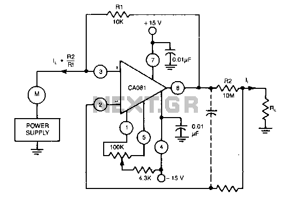
This circuit utilizes a CA018 BiMOS operational amplifier. A low current, supplied at the input potential as a power supply to the load resistor RL, is amplified by the resistor ratio R2/R1, while the load current h is monitored...
This project indicates the audio volume level going to speakers by illuminating LEDs. The LEDs can be of any color, allowing for creative combinations. The circuit input is connected to the speaker output of an audio amplifier. Two identical...
The second transistor (T2) is activated by the current passing through the resistor (R1). When a DALI slave unit is connected, this current matches the current flowing through the power transistor (T1). The resistor's value is selected so that...
While conducting background research on the Philips I2C bus, an application note authored by Herman Schutte from Philips Semiconductors Systems Laboratory in Eindhoven was discovered. Mr. Schutte detailed an efficient method for interfacing sections of the I2C bus operating...
The circuit diagram represents a simple yet effective intercom system entirely based on transistors. It consists of three stages along with an RC amplifier. When the pushbutton S2 is pressed, the amplifier circuit around transistor T1 is activated. The intercom...
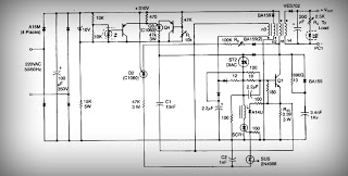
This is a low voltage, high-current output switching DC power supply with an input of 220 volts AC. In this circuit, an ST2 DIAC relaxation oscillator, Q3, C1, and the DIAC initiate conduction of the output switching transistor Q1....