
Simple Intercom Circuit Transistor
The intercom circuit utilizes three transistor stages to amplify audio signals, ensuring clear communication between the stations. The first stage typically involves a microphone connected to the base of the first transistor (T1), which serves as a pre-amplifier. This stage is crucial for picking up the audio signals and converting them into electrical signals.
The second stage amplifies the signal further, using a second transistor (T2) configured in a common emitter arrangement. This configuration provides additional gain and helps to drive the next stage of the circuit. The output from T2 is then fed into an RC (resistor-capacitor) filter that smooths out the signal and eliminates any high-frequency noise that may interfere with audio clarity.
The final stage, which involves the third transistor (T3), acts as a driver stage to power the speaker or output device. This transistor also ensures that the audio signal is strong enough to be heard clearly at the receiving end of the intercom system. The pushbutton switch S2 serves as a control mechanism, allowing the user to activate the circuit and initiate communication.
In summary, this transistor-based intercom circuit design effectively amplifies audio signals through a three-stage amplification process, with the RC filter enhancing signal quality, making it suitable for reliable intercom applications.Circuit diagram is a simple but effective circuit intercom circuit is based entirely on transistors. Circuit diagram is based on three stages plus RC amplifier. When the pushbutton S2 is pressed, the amplifier cord around T1 . 🔗 External reference
Related Circuits
This solid-state push-pull single-ended Class A circuit is capable of providing sound quality comparable to valve amplifiers, delivering an output power of 6.9W measured across an 8 Ohm loudspeaker cabinet load. It exhibits lower total harmonic distortion (THD), higher...
This circuit will flash a bright red LED (5000 mcd) as an attention-getting device or fake car alarm. Component values are not critical, and other transistors may be used. The flash duration is determined by R2 and C1 and...
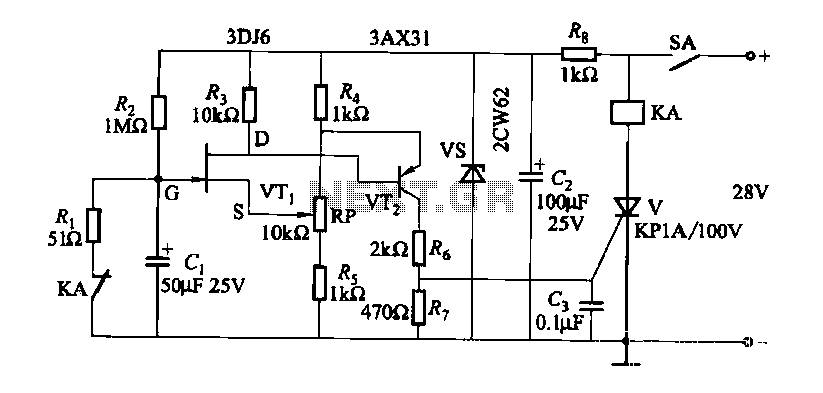
FET relay circuit 2 is essentially a JS-20 time relay circuit. When the switch SA is open, the relay device KA remains in the released state. Once switch SA is closed, the delay period begins. After a specified duration,...
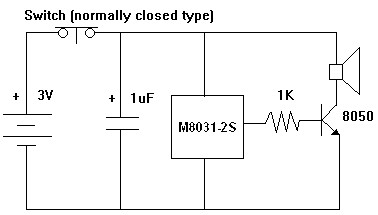
The M8031 circuit features an integrated RC oscillator and digital envelope circuits, which minimize the need for external components. It produces a sound that mimics a mechanical ding-dong. The M8031 operates with a low input voltage range of 1.3...
A wide range auto turn OFF timer covering 1 minute to 20 hours in three ranges with S1. As soon as power is applied to the circuit, the IC1 [555] starts to oscillate and feeds clock pulses to the...
A bandpass filter allows a specific range of frequencies to pass while rejecting frequencies that fall outside the upper and lower limits of the passband. The frequencies that are permitted to pass are referred to as the passband, which...
Warning: include(partials/cookie-banner.php): Failed to open stream: Permission denied in /var/www/html/nextgr/view-circuit.php on line 713
Warning: include(): Failed opening 'partials/cookie-banner.php' for inclusion (include_path='.:/usr/share/php') in /var/www/html/nextgr/view-circuit.php on line 713