
CW117 CW217 CW317 schematic configuration of the constant voltage constant current source

The constant voltage/current power supply is a crucial component in various electronic applications, providing stable and adjustable power to circuits. The architecture includes a combination of linear regulation and current limiting, ensuring that the output voltage and current remain within specified limits regardless of load variations.
The two 3CF5 transistors are configured in parallel to enhance the current handling capability of the power supply. This configuration allows for better thermal management and increased reliability, as the load current is shared between the transistors. The use of a limiting resistor (R3) is essential for protecting the transistors from excessive current, which could lead to thermal runaway and potential failure.
The potentiometers R2 and R are integral to the functionality of the power supply. R2, the current adjustment potentiometer, allows the user to set the desired output current up to 5A. This feature is particularly beneficial in applications where precise current control is necessary, such as in battery charging or LED driving. R, the voltage adjustment potentiometer, enables the user to select the output voltage within the range of 1.25V to 30V, accommodating a wide variety of electronic devices.
The integrated high-current power supply circuitry ensures that the power supply can maintain stable output under varying load conditions. It employs feedback mechanisms to continuously monitor output parameters and adjust the control elements accordingly. This design not only enhances performance but also improves the overall efficiency of the power supply.
In summary, this constant voltage/current power supply box design effectively combines robust components and adjustable features to deliver reliable and precise power for various electronic applications. Its ability to provide both regulated voltage and current makes it an essential tool for engineers and technicians in the field of electronics. As shown is a constant voltage/current power supply box diagram. It consists spread current, constant voltage and constant current of three parts. 3CF5 two power transistors in parallel as an extension tube; resistor R3 is limiting resistor; R2 is a current adjustment potentiometer; R is a voltage adjustment potentiometer. The power supply works with the integrated high-current power supply and the same constant current source can provide 1.25 ~ 30V regulated output voltage and constant current output 0 ~ 5A.
Related Circuits
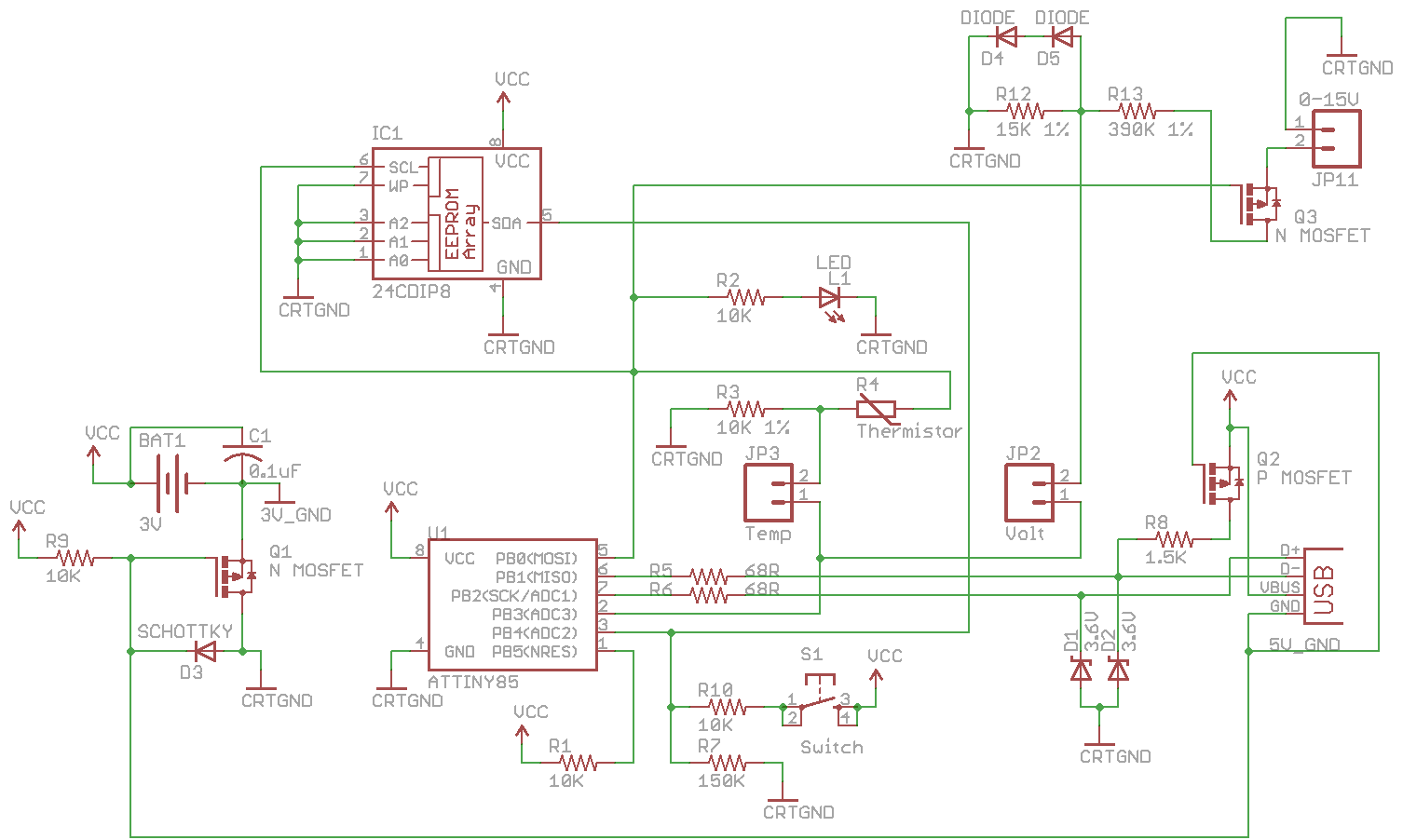
Combine the SATL and SAVL together. The schematic was updated with the voltage sensing circuit. A MOSFET was added to draw power from the voltage source only when needed. There are two jumpers, Temp and Volt, allowing the user...
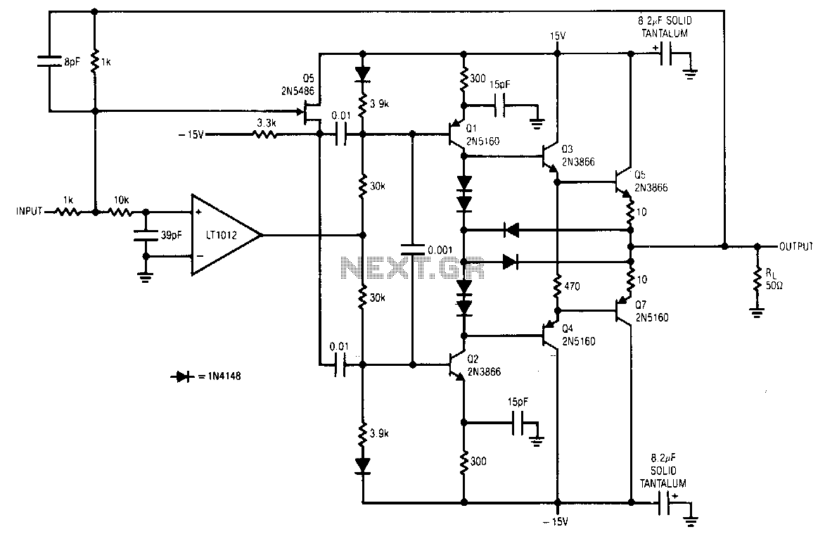
The LT1012 corrects errors in the booster stage and does not set high-frequency signals. Fast signals are fed directly to the stage via Q5 and the 0.01 µF coupling capacitors. DC and low-frequency signals drive the stage via the...
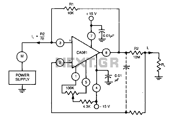
This circuit utilizes a CA018 BiMOS operational amplifier. A low current, supplied at the input potential as a power supply to the load resistor RL, is amplified by the resistor ratio R2/R1, while the load current h is monitored...
To alleviate any concerns related to high frequency, a ready-made Aurel audio FM transmitter module has been utilized. This compact circuit board, measuring 2 cm by 4 cm, supports a modulation frequency track and delivers an RF power of...
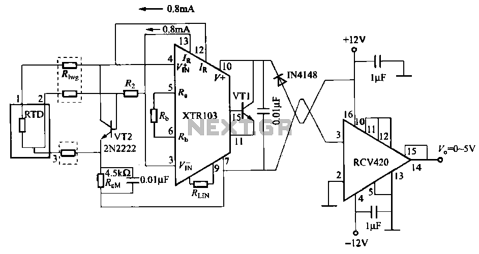
When the RTD temperature sensor is positioned far from the amplifier, the resistance of the sensor leads and their susceptibility to interference and other issues cannot be overlooked. The circuit shown in the figure addresses this problem. It utilizes...
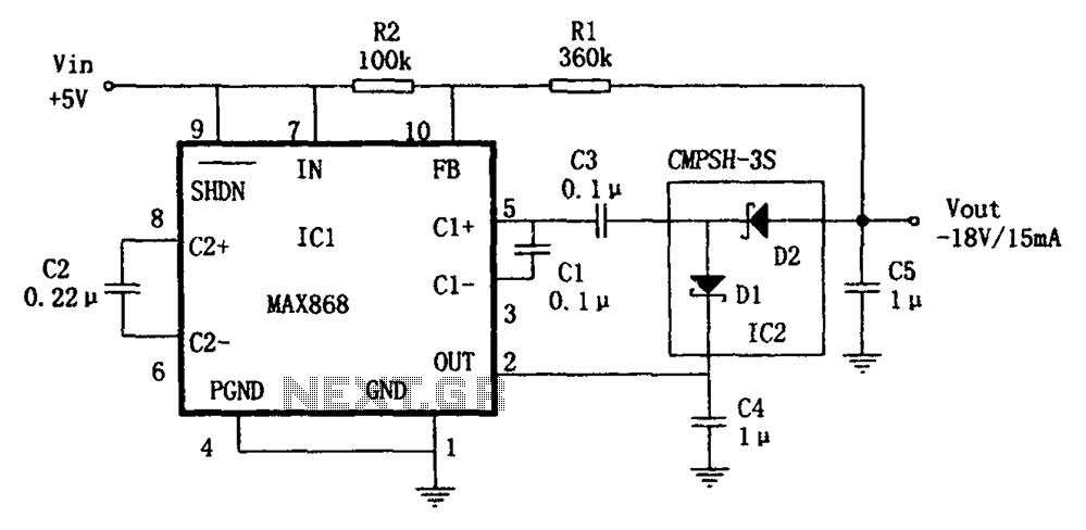
The circuit utilizes the IC1 MAX868 and CMPSH-3S to create a quadruple voltage DC/DC converter power supply. The IC1 MAX868 is an inverting charge pump regulator integrated circuit that can generate an output voltage of up to -2VIN, with...