
Daft Punk Coffee Table 5x5 LED Matrix using an Arduino
The circuit design described involves a matrix of white LEDs arranged in a grid format, controlled by an Arduino microcontroller. The matrix utilizes a multiplexing technique to drive the LEDs, allowing for efficient control while adhering to current limits. Each LED is connected in such a way that only a fraction of the total matrix is illuminated at any given time, which reduces the overall current draw and prevents damage to the components. The use of current limiting resistors is critical to ensure that the forward current through each LED remains within safe limits, thereby enhancing the longevity and reliability of the entire setup.
The assembly process involves careful cutting and gluing of foam board to create the structural framework for the LED matrix. The grid design allows for easy insertion of the LEDs and ensures consistent orientation, which simplifies the wiring process. The implementation of diagonal slits for the LED pins not only aids in wiring but also minimizes the risk of short circuits, which can occur with more conventional wiring methods.
In terms of electrical characteristics, the selection of appropriate resistors is essential for limiting the current through the LEDs. The calculated resistance values should be adjusted based on the actual forward voltage drop of the LEDs and the supply voltage used in the circuit. The inclusion of blocking diodes is a crucial modification to prevent unintended current flow through the LEDs, particularly in configurations where reverse bias could lead to high leakage currents.
Testing and troubleshooting are integral to the development process. The ability to cycle through the LEDs in a controlled manner allows for easy identification of wiring errors and ensures that the matrix functions as intended before final assembly. In cases where multiple LEDs illuminate erroneously, the design includes provisions for corrective measures, such as adjusting the wiring or adding additional components like blocking diodes.
Overall, this project exemplifies a practical application of LED technology combined with microcontroller programming, showcasing both the challenges and solutions encountered in designing an efficient LED matrix display. The attention to detail in the assembly and electrical design ensures a robust and reliable final product.You may need also need 10 diodes and different resistors, especially if you are using white LED`s please the Troubleshooting section in step 3 for details. . 005 ³ thick matte drafting film I bought a sheet from a local artist`s supply store. The smallest sheet they had was way more than I needed 24G—36 ³ The LED`s I used were po int source water clear. If you don`t want to deal with hotspots in your display, diffused would be better. I had to put blobs of hot glue on mine to diffuse them. The photo below only shows bits of the foam board, because I forgot to photograph the parts before I started. The piece I used was about 16G—20 ³ to start with. I used foam board, which was recycled from one of my kids` science fair projects. It is a sandwich of white paper with a foam core, 3/16 ³ thick. The overall size is approximately of our project is approximately 10x10x2 ³. I cut the parts with a mat knife, and hot glued it together. To make the grid, cut 8 identical 2G—10 ³ pieces. Then cut 4 equally spaced slits into each one. The slits should be 1 ³ deep, the same width as the foam board. Interlock the pieces to create the 5G—5 grid. Finally, cut the 2 (10 3/8)x2 ³ pieces for the top and bottom. My foam was 3/16 ³ thick, so I had to add 3/8 ³ tothe length to make them long enough to cover the sides.
Hot glue them on. Note that in the photo below which includes the top & bottom & sides, the LED`s are already installed and wired up. This is because I didn`t attach the top/bottom/sides until I was in the testing phase, but it`s easier to deal with if you glue them on earlier in the process.
Cut small diagonal slits in the center of each cell, and insert one LED in each cell. Make sure to orient them the same way in each cell. This will make it less confusing when wiring it up. I laid mine out w/ the flat side (cathode) facing the bottom right corner. Using diagonal slits for the pins makes it easier to wire it up without shorting the wires, since we are going to wire While one can use any of the I/O pins on the Arduino, I chose the pins specifically to allow me to use very compact code to turn on the columns. This will be explained in detail later. The anodes are connected to pins. Some existing designs, such as the o ne in the Arduino Playground don`t bother to use current limiting resistors.
This is not a good design practice, and can result in burned out LED`s, or worse yet, a burned out Arduino. Each I/O pin on the Arduino can source or sink up to 40mAof current. The LED`s which I used have the following electrical characteristics: Plugging in the values, we get R = (5 3.
3) /. 02 = 85 ohms. The nearest available standard resistor value is 100 ohms. Always round up instead of down, because if you round down, you will exceed the maximum allowable current. Notice that we only use 5 resistors. We don`t have to put one at each LED, because we will only be driving one row, a maximum of 5 LED`s at a time.
I said above that each I/O pin can drive 40mA of continuous current, so why can`t we drive the whole LED array at once It`s because another constraint is that the total drive current summed up across all the pins can`t exceed 200mA. If we turn on all 25 LED`s at once, then 25*20mA = 500mA flow, which is way over spec. So maybe we can turn on 1 row at a time, and scan the rows, like the way a CRT works If we turn on a whole row of LED`s at once, the current is 20mA * 5 = 100mA.
This, at first, appears to be OK, because each column (anode) pin is only sourcing 20mA, and we`re below the Atmega368P`s total 200mA current limit. However, upon more analysis, we can`t even drive 5 LED`s at once. Why Because the cathodes of all 5 LED`s in a row are connected together into a single I/O pin, and we`re not allowed to sink more than 40mA per pin.
Therefore, we will write our software so that no more than 2 LED`s are turned on at a time, so the row (cathode) pins will sink a maximum of 40mA each. Now, even though we`re at the allowable continuous current limit, it`s generally not good practice to run a device at its maximum limits.
However, since we`re going to pulse each LED briefly, and let persistence of vision create the illusion that they`re all on at once, it`s OK. Note: I tried running mine w/ 5 LED`s lit per row for several hours, and it worked fine, but it`s always best to design your circuits within specifications, to ensure long term reliability.
If your matrix doesn`t function properly, first, you should double check your wiring. The sketch also has a testing mode, which cycles through the LED`s one by one slowly enough that you can see it. You can enable it by uncommenting the following line in the sketch: One potential mistake is accidentally swapping the columns and rows.
If your matrix looks like this video in TESTMODE, then you`ve made this error, and need to swap the row and column connections to your Arduino. Thanks to Instructables user 303_addict for posting the video. If your wiring is correct, and you are getting more than one LED at a time lighting up, you might be one of the unlucky ones who has LED`s that have a high leakage current when reverse biased.
White LED`s are particulary susceptible to this problem. If this is the case, you will need to add series blocking diodes on the inputs to all the columns, as well as on all the row outputs. So you will need 10 diodes. Any small signal diode will work, such as 1N4001, 1N914, 1N4148, etc. You will also need to adjust the resistor values, because two series diodes will add ~1. 4V voltage drop. So in my equation above, use 3. 6 for VCC. For my 3. 3V LED`s you end up with R = (5-1. 4-3. 3V)/20mA = 15 ohms. I didn`t have any 15 ohm resistors handy, so I substituted 10 ohms instead, and using an ammeter, measured 19.
5mA. still within spec. See the last attached image. 🔗 External reference
Related Circuits

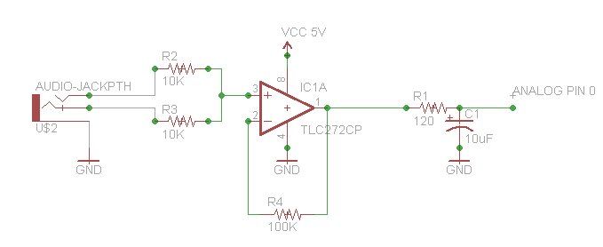
This is a simple toggle switch that can be operated through sound signals such as a whistle or clap. The output of the toggle remains either low or high until... This circuit utilizes a sound sensor to detect specific audio...
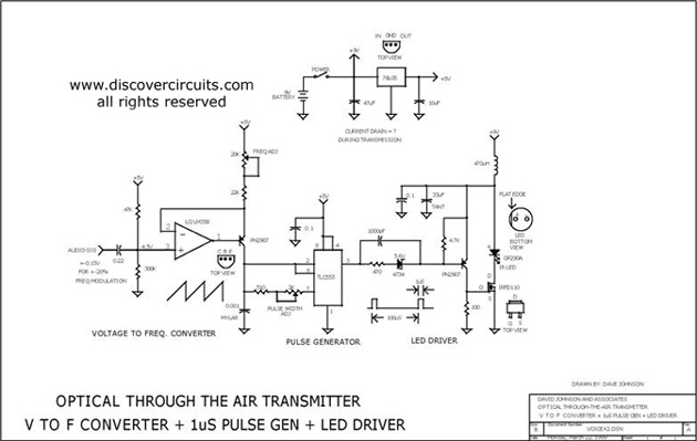
This circuit receives the signal from the amplifier and emits powerful 1μs infrared light pulses from a low-cost LED, which are frequency modulated by the audio information. The 10kHz center frequency of the pulse stream is sufficiently low, allowing...
A motor spins the "propeller", and a small microprocessor keeps track of time and changes the pattern on seven LEDs with exact timing to simulate a 7 by 30 array of LEDs. It is an illusion, but it works...
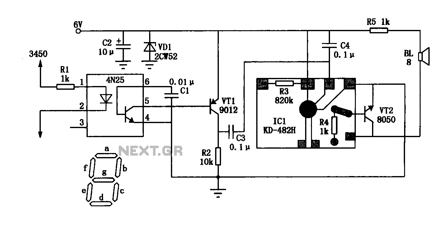
The General Dynamic LED digital clock lacks a timekeeping function, but by adding a simple circuit, it can incorporate this feature. The integrated circuit (IC) includes a programmable mute function, which is inactive from 23:00 to 5:00 to avoid...
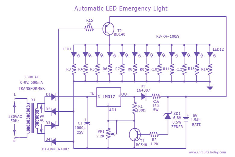
This is a cost-effective and straightforward emergency light circuit developed for CircuitsToday. It is an automatic emergency lamp with daylight sensing capabilities, meaning it detects darkness and turns on automatically, while also sensing daylight to turn off. The circuit...
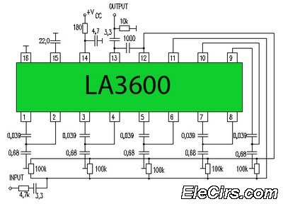
Circuit LA3600 5 Band Equalizer Circuit Schematics. One type of tone control in audio electronics is the graphic equalizer. Graphic equalizers can be categorized into two types: bar and other configurations. The LA3600 circuit is a 5-band graphic equalizer designed...