
DARLINGTON TRANSISTOR OSCILLATOR

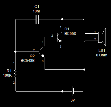
The oscillator circuit described is characterized by its unique design, which incorporates a one-turn coil (L1) crafted from #12 gauge wire. This wire is formed into a loop with a diameter of 12 inches, creating a substantial inductive element. The large capacitance-to-inductance ratio is a critical feature, as it allows the oscillator to operate effectively at lower frequencies, which is ideal for applications like metal detection.
In metal detectors, the loop antenna serves as both the transmitter and receiver of electromagnetic waves. The oscillator generates a continuous wave signal that is transmitted through the loop. When metal objects are present within the detection field, they alter the electromagnetic field, causing variations in the received signal. These variations are then processed to identify the presence and type of metal.
The circuit may also include additional components such as capacitors, resistors, and diodes, which help to stabilize the oscillator's frequency and improve overall performance. The choice of components and their values will depend on the specific application requirements, including sensitivity and range.
Overall, the oscillator circuit's design is tailored for efficient operation in metal detection applications, leveraging the properties of the large loop antenna and the specific inductance and capacitance values to optimize performance.This oscillator uses a very large capacitance-to-inductance ratio. L1 is a one-tum coil consisting of a loop of #12 wire 12 in diameter. This circuit is useful for metal detectors, etc., where a loop antenna is used.. 🔗 External reference
Related Circuits
This is a sine wave oscillator circuit, also known as an amplitude-stabilized sine-wave oscillator. It can provide a high purity sine wave output. The sine wave oscillator circuit is designed to generate a stable and high-quality sine wave output, which...
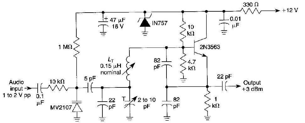
This FM oscillator can be utilized for wireless audio, microphone, and part-15 applications where a stable frequency-modulated oscillator is required. The FM oscillator is an essential component in various communication systems, particularly in wireless audio transmission and microphone applications. It...
This circuit is a conventional Pierce type oscillator that utilizes a JFET. It operates with fundamental mode crystals and exhibits good performance and reliability when a low noise JFET is employed. The feedback is regulated by the capacitance of...
The Hartley Oscillator is a valuable circuit for generating high-quality sine wave signals in the RF range (30 kHz to 30 MHz). However, at the upper limits of this range and beyond, the Colpitts oscillator is typically favored. Both...
This is the first oscillator that was built. Various resources such as books, magazines, and online schematics were reviewed. Most of the designs encountered were either Colpitts or Hartley oscillators. While these designs are relatively straightforward, they require specific...
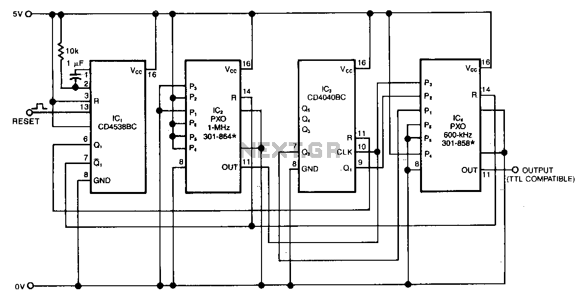
The swept-frequency oscillator provides a cost-effective source of discrete frequencies for testing digital circuits. This configuration generates an 80-second sequence of eight frequencies, with each frequency maintained for 10 seconds. The dwell time and the number of frequencies can...