
The Hartley Oscillator
The Hartley oscillator circuit consists of several key components: a tapped inductor, a capacitor, and a transistor configured as a common base amplifier. The tapped inductor, comprising L1 and L2, is crucial for determining the frequency of oscillation. The inductive portion is connected to the collector of the transistor, while the capacitor C3 is connected to ground. This configuration forms a resonant tank circuit, which is responsible for generating the oscillation frequency.
The operation of the Hartley oscillator begins with the initial conditions set by the circuit components. When power is applied, the transistor begins to conduct, and the tank circuit starts oscillating at its resonant frequency. The feedback mechanism is critical for sustaining oscillation; the voltage from the collector is fed back to the emitter through C2, ensuring that the amplifier's output supports the oscillation.
The phase relationship between the output and input signals is essential for maintaining stable oscillations. The common base configuration allows for a high-frequency response while ensuring that the output and input remain in phase. The automatic gain control provided by the feedback loop via R3 and C2 stabilizes the amplitude of the oscillation, preventing distortion and maintaining a clean sine wave output.
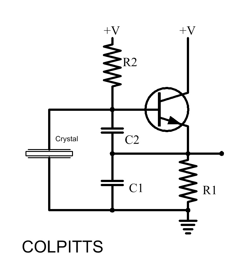
In summary, the Hartley oscillator is a widely used circuit for producing sine wave signals in the RF range, characterized by its unique use of a tapped inductor and a common base amplifier configuration. Its ability to generate low-distortion sine waves makes it suitable for various applications in communication systems and signal processing.The Hartley Oscillator is a particularly useful circuit for producing good quality sine wave signals in the RF range, (30kHz to 30MHz) although at the higher limits of this range and above, The Colpitts oscillator is usually preferred. Although both these oscillators oscillator use an LC tuned (tank) circuit to control the oscillator frequency, Th
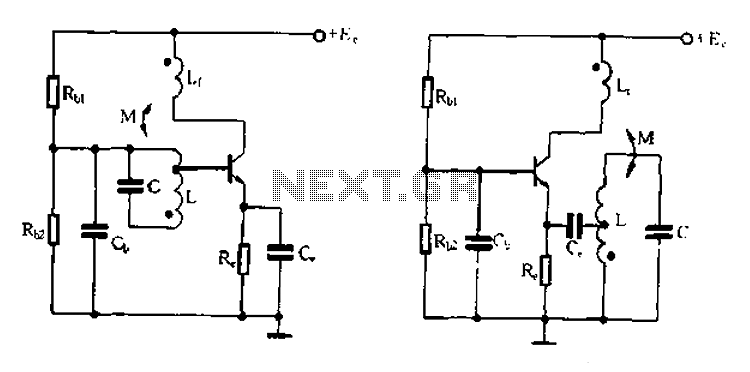
e Hartley design can be recognised by its use of a tapped inductor (L1 and L2 in Fig. 2. 1. 1). Fig. 2. 1. 1 shows a typical Hartley oscillator. The frequency determining resonant tuned circuit is formed by L1/L2 and C3 and is used as the load impedance of the amplifier. This gives the amplifier a high gain only at the resonant frequency (Method 2 in Introduction to Oscillators).
This particular version of the Hartley circuit uses a common base amplifier, the base of TR1 being connected directly to 0V (as far as AC the signal is concerned) by C1. In this mode the output voltage waveform at the collector, and the input signal at the emitter are in phase.
This ensures that the fraction of the output signal fed back from the tuned circuit collector load to the emitter via the capacitor C2 provides the necessary positive feedback. C2 also forms a long time constant with the emitter resistor R3 to provide an average DC voltage level proportional to the amplitude of the feedback signal at the emitter of Tr1.
This is used to automatically control the gain of the amplifier to give the necessary closed loop gain of 1. The emitter resistor R3 is not decoupled because the emitter terminal is used as the amplifier input.
The base being connected to ground via C1, which will have a very low reactance at the oscillator frequency. The LC circuit that controls the frequency of oscillation is often called the "TANK CIRCUIT" because it contains circulating currents much greater than the current supplying it (e.
g. pulses of collector current supplied by the amplifier). Its operation is supposed to be rather like a water tank or cistern that can supply a continuous flow of water from an intermittently flowing external supply. The tank circuit in the oscillator contains high values of circulating current topped up regularly by smaller amounts of current from the amplifier.
Because most of the current flowing in the oscillator is flowing just around the resonant tank circuit rather than though the amplifier section of the oscillator, LC oscillators generally produce a sine wave with very little amplifier sourced distortion. Another feature of the tank circuit is to provide the correct amount of positive feedback to keep the oscillator running.
This is done by dividing the inductive branch of the circuit into two sections, each having a different value, the inductor therefore works in a similar manner to an autotransformer, the ratio of the two windings providing the appropriate amount of signal to be fed back to the input of the amplifier. Because in Fig. 2. 1. 2 (and Fig. 2. 1. 1) the top of L1 is connected to +Vcc, it is, as far as AC signals are concerned, connected to ground via the very low impedance of C5.
Therefore waveform X across L1, and waveform Y across the whole circuit are in phase. As a common base amplifier is being used, the collector and emitter signals are also in phase, and the tank circuit is therefore providing positive feedback. In other Hartley designs, using common emitter amplifiers for example, similar tank circuits are used but with different connections, so that the feedback signal is always in phase with the input signal, therefore providing the necessary positive feedback.
It is common in LC sine wave oscillators to use automatic class C bias. In class C the bias voltage, that is the base voltage of the transistor is more negative than the emitter voltage, making Vbe negative so that the average (centre) voltage of the input wave is located on the negative portion of the Vbe axis of the characteristic curve show 🔗 External reference
Related Circuits
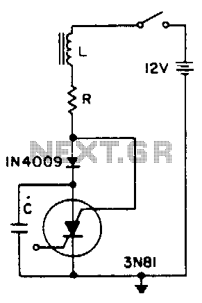
A positive transient, such as the power switch closing, charges through L to a voltage above the supply voltage, if Q is sufficient. When the current reverses, the diode blocks and triggers the SCS. As the capacitor discharges, the...
Inquiries about selecting the L, C, and R values to achieve a desired frequency are common. It is essential to understand the relationship between these components and the frequency they produce. The desired frequency can be calculated using the...
The RF engineer often needs an instrument that can reliably and quickly check a low-frequency quartz crystal unit. However, such equipment is challenging to find, and engineers frequently refer to electronic circuit handbooks for schematics that can perform this...
Its frequency depends on the capacitance of the vary cap diode. The center frequency is changed by varying the biasing voltage of the vary cap through the 47K pot. You can use a 75cm telescopic antenna or simply a...
Base frequency selection, frequency-selective emitter type transformer coupled oscillator circuit The described circuit is a transformer-coupled oscillator that utilizes an emitter type configuration to achieve frequency selection. This type of oscillator is designed to generate signals at specific base frequencies,...
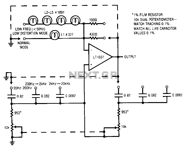
A variable Wien bridge provides frequency tuning from 20 Hz to 20 kHz. Gain control comes from the positive temperature coefficient of the lamp. When power is applied, the lamp has a low resistance value, resulting in high gain...