
DC motor 12V speed controller circuit with explanation
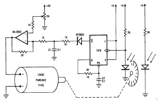
The described encoder circuit operates as a feedback control system for a DC motor, utilizing the HA-2542 operational amplifier to maintain the desired speed efficiently. The position encoder is critical in this setup, as it translates the motor's rotational position into electrical pulses. These pulses are characterized by a consistent width, allowing for precise timing and frequency measurement.
The capacitor CI serves as a charge storage element, integrating the pulses from the encoder to produce a smooth voltage signal that reflects the average speed of the motor. This voltage is then fed into the inverting input of the HA-2542. The non-inverting input is set to a reference voltage, which can be adjusted to represent the target speed of the motor. The operational amplifier compares these two signals, and any difference results in an output that adjusts the motor's drive signal accordingly. This feedback mechanism ensures that the motor operates at the desired speed, compensating for any variations due to load changes or other factors.
In terms of component selection, the HA-2542 is chosen for its high performance in terms of gain and bandwidth, making it suitable for real-time speed control applications. The circuit's simplicity is advantageous, as it minimizes the number of external components required, which can lead to reduced complexity and cost.
The limitations mentioned regarding the encoder wheel can be addressed by employing a pulley system. By attaching a pulley to the encoder wheel, it becomes possible to use the motor's output to drive another device, such as a conveyor belt or a fan. This versatility allows the circuit to be applied in various applications beyond just motor speed control, enhancing its utility in automated systems. The use of a belt to connect the motor to other devices provides a mechanical means to transfer motion and control speed, further expanding the functionality of the circuit.A very simple encoder circuit for a dc motor can be constructed using this circuit diagram. As you can see in the circuit diagram, the system shown consists of the HA-2542, a small 12-Vdc motor, and a position encoder. During operation, the encoder causes a series of ``constant-width" pulses to charge CI. The integrated pulses develop a referenc e voltage, which is propor £ional to motor speed and is applied to the inverting input of HA-2542, The noninverting input is held at a constant voltage, which represents the desired motor speed. A difference between these two inputs will send a corrected drive signal to the motor, which completes the speed control system loop.
As you can see the circuit requires few external components, but because of the encoder wheel it has a limitations of use. If you put a pulley under the encoder wheel you can command the speed of other device, by connecting the (motor and other device ) using a belt
🔗 External reference
Related Circuits
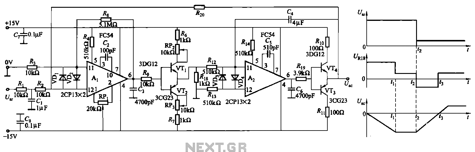
The ZKJ-S-type buffer controller circuit is designed for motor starting slip control. This buffer controller is composed of two operational amplifiers, Ai and Az. The operational amplifier Ai functions as a speed amplifier that saturates, while Az acts as...
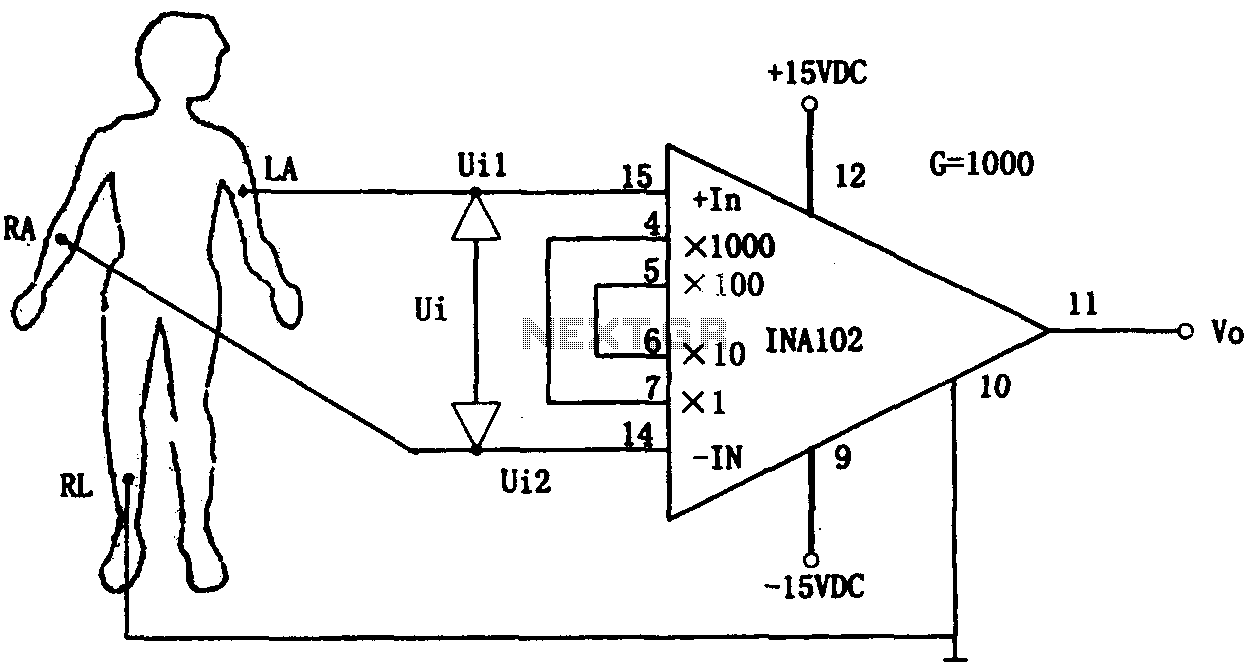
This document outlines a preamplifier circuit designed for measuring human biological signals, such as ECG and EEG. These biological signals are typically weak and require high amplification circuits. The circuit utilizes a low-power integrated operational amplifier, INA102. The INA102...
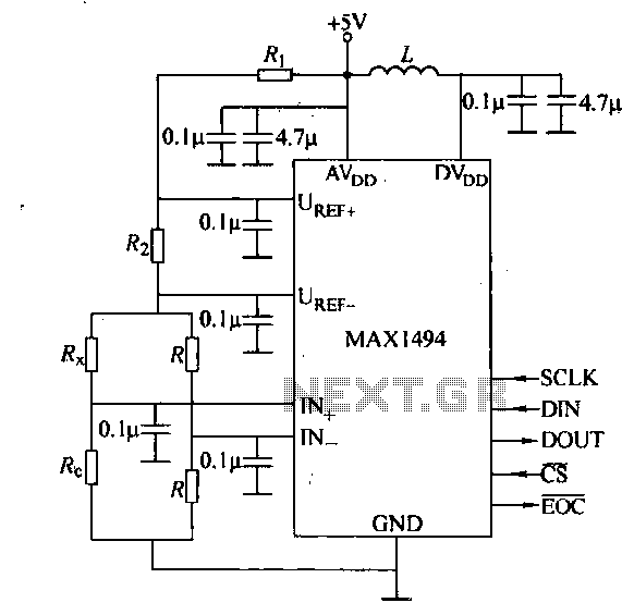
The circuit consists of the MAX1494 digital strain gauge, as illustrated in Figure 5-31. It includes a bridge formed by resistance strain gauges and a temperature compensation sheet. The standard quasi-resistance values Rl and R are incorporated into the...
The circuit is designed for a broadband linear detection application with a bandwidth of 10 MHz. It serves as a millivoltmeter measuring instrument suitable for frequencies exceeding 10 MHz. The circuit features a linear detector utilizing operational amplifiers, specifically...
All resistors have a tolerance of 5 or 10 percent and are rated for 1/4 watt. All capacitors have a tolerance of 10 percent and are rated for 35 volts or higher. This circuit effectively amplifies the output of...
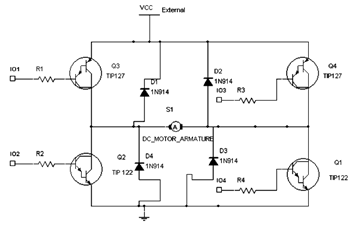
The diagram below illustrates an H-Bridge circuit featuring four inputs and an external power supply. The control application must enable the motor to operate in both forward and reverse directions. The H-Bridge is a crucial component in motor control applications,...
Warning: include(partials/cookie-banner.php): Failed to open stream: Permission denied in /var/www/html/nextgr/view-circuit.php on line 713
Warning: include(): Failed opening 'partials/cookie-banner.php' for inclusion (include_path='.:/usr/share/php') in /var/www/html/nextgr/view-circuit.php on line 713