
Digital circuit strain with MAX1494

The MAX1494 is a highly integrated digital strain gauge interface designed to measure strain by using a bridge configuration of resistive strain gauges. The strain gauges convert mechanical deformation into a change in resistance, which is then translated into a voltage signal. The internal reference voltage provided by the MAX1494 is critical for ensuring accurate measurements, as it stabilizes the voltage across the bridge and allows for precise differential measurements.
In this circuit, the bridge is typically formed by four strain gauges arranged in a Wheatstone bridge configuration. This arrangement allows for the detection of small changes in resistance due to strain, enhancing sensitivity and accuracy. The temperature compensation sheet is essential for minimizing the effects of temperature variations on the strain gauge readings, ensuring that the measurements reflect only the mechanical strain.
The output voltage of the bridge, which varies between 200 mV and 2 V, is fed into the differential input of the MAX1494. This voltage range is suitable for various applications, including structural health monitoring, load cells, and pressure sensors. The MAX1494's internal circuitry amplifies and digitizes the analog signal from the strain bridge, providing a digital output that can be easily interfaced with microcontrollers or other digital systems for further processing and analysis.
In summary, the circuit utilizing the MAX1494 digital strain gauge is a robust solution for measuring strain with high precision, leveraging the advantages of a bridge configuration, temperature compensation, and digital signal processing capabilities.Circuit constituted by the MAX1494 digital strain gauge shown in Figure 5-31. See the bridge by the resistance strain gages, temperature compensation sheet R, standard quasi resistance Rl and R l trespassing into. Bridge voltage provided by the MAX1494's internal reference voltage, MAX1494 differential input termination strain bridge output voltage, the voltage range of soil 200mV- 2V.
Related Circuits
This project involves a ding-dong doorbell circuit utilizing the 555 Integrated Circuit (IC). In a previous article, a simple doorbell circuit using the UM66 IC, a CMOS three-terminal melody IC, was discussed. The current circuit employs the NE555 IC...
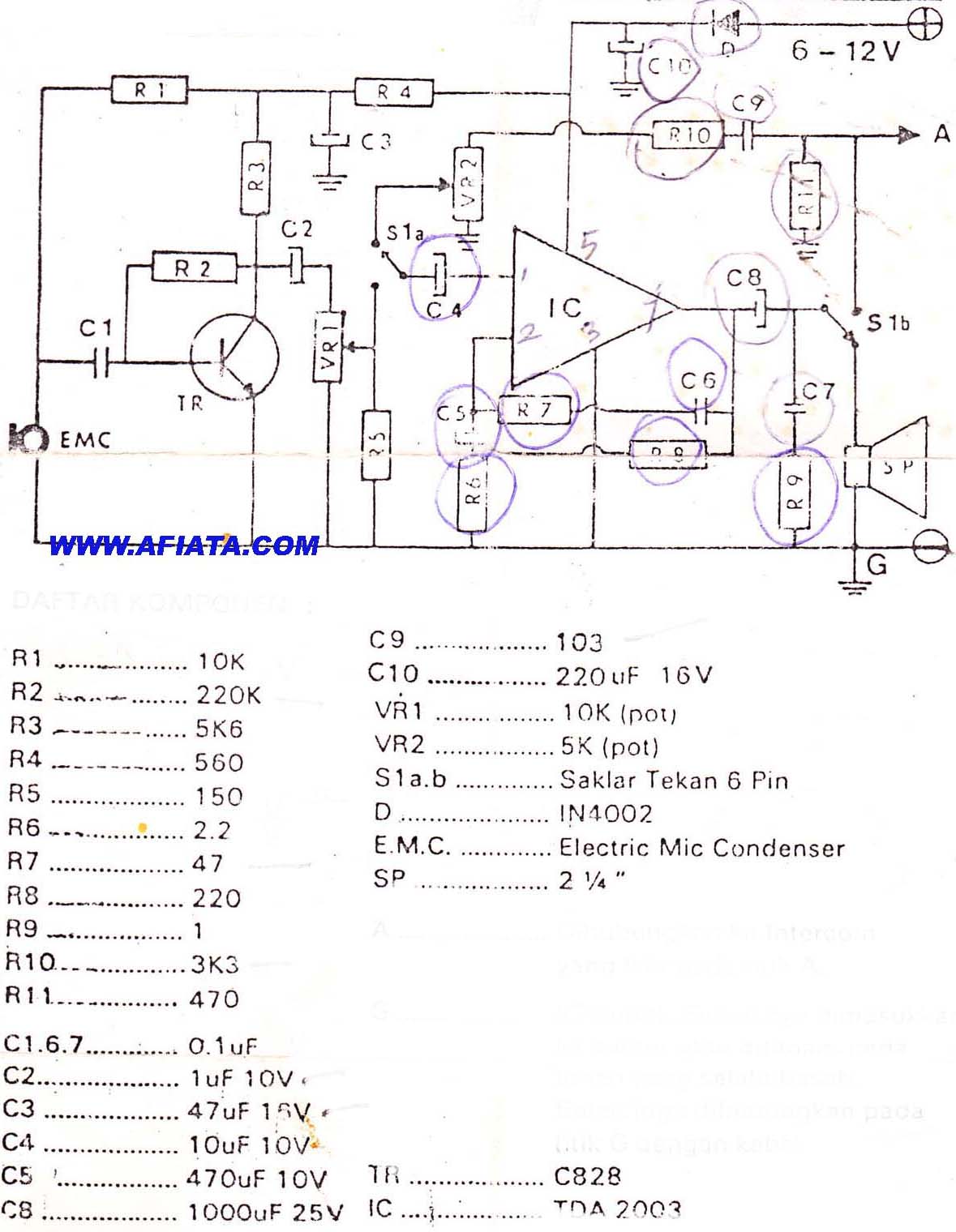
DIY Intercom Circuit Full-duplex intercom circuit schematic, cable on the way to the intercom circuit. The DIY intercom circuit is designed to facilitate two-way communication using a full-duplex system. This allows simultaneous transmission and reception of audio signals, enabling clear...
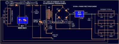
Most peripherals that interface with a PC utilize a USB port. The computer's power supply circuit, specifically the switched-mode power supply (SMPS), is designed to provide constant power to all internal components. However, when external peripherals that require a...
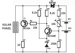
The nominal voltage of the solar charger circuit module is determined by the number of battery cells to be charged. Due to the typical voltage drop of 0.3 to 0.4 V across Schottky diode D1, the nominal voltage should...
This circuit provides a visual 9-second delay using a 7-segment digital readout LED. When the switch is closed, the CD4010 up/down counter is preset to 9, and the 555 timer is disabled, holding the output high. When the switch...
This time, we will share information about Yo3dac's homebrew RF circuit design ideas, including the latest updates from Onmilwiki. Yo3dac is known for innovative approaches in the realm of radio frequency (RF) circuit design, particularly within the homebrew community. The...
Warning: include(partials/cookie-banner.php): Failed to open stream: Permission denied in /var/www/html/nextgr/view-circuit.php on line 713
Warning: include(): Failed opening 'partials/cookie-banner.php' for inclusion (include_path='.:/usr/share/php') in /var/www/html/nextgr/view-circuit.php on line 713