
DC Motor Direction Controller

To control a small DC motor effectively, a circuit utilizing transistors Q1 and Q2 is employed. In this configuration, Q1 and Q2 serve as switches that regulate the flow of current to the motor based on the logic levels applied to points A and B. When both points A and B are set to a HIGH state, both transistors enter saturation, allowing maximum current to flow through the motor.
The circuit typically includes additional components such as resistors to limit the base current to the transistors, ensuring they operate within their safe limits. A diode may also be included in parallel with the motor to provide flyback protection, preventing voltage spikes generated when the motor is turned off from damaging the transistors.
The power supply for the motor should be selected based on the motor's voltage rating to ensure proper operation. The design may also incorporate feedback mechanisms, such as a rotary encoder, to monitor the motor's position or speed, allowing for more precise control.
This arrangement is widely used in various applications where small DC motors are required, including robotics, automation systems, and consumer electronics, due to its simplicity and effectiveness in controlling motor operation.For control a small DC motor, like the one in a tape recorder. Q1 and Q2 are in saturation when both the points A & B are `HIGH`. Component: .. 🔗 External reference
Related Circuits
LBl690 is a three-phase brushless DC motor drive control integrated circuit manufactured by Sanyo, a Japanese company. It is extensively utilized in both domestic and imported applications for broken wind and fresh air conditioning systems that require brushless DC drive...
Camping today often requires carrying various electronic devices for daily activities and entertainment. Typically, a charged lead-acid battery and a power inverter are utilized to ensure a well-organized trip, allowing family members to use their electronic devices comfortably. It...
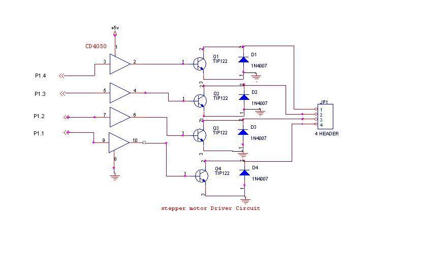
A 6V, 2A stepper motor is utilized in this circuit. The CD4050 hex buffer is employed to connect to the microcontroller. The output of the CD4050 is linked to the base of a TIP122 transistor. The emitter and collector...
Electric motors have been widely used for motion control, and various types of motor controllers have been designed to provide variable speed drives for these motors. Electric motors are integral to numerous applications requiring precise motion control, ranging from industrial...
This Project can be used with the three phase Induction motors. The circuit will take the full control of the motor and it will protect the motor from several faults such us over voltage and under voltage and the...
Camping today often requires bringing various electronic devices for daily activities or entertainment. Frequently, a charge is needed for these devices. In modern camping scenarios, the reliance on electronic devices has significantly increased. Campers typically bring smartphones, tablets, GPS devices,...