
Car and Motorcycle Battery Tester
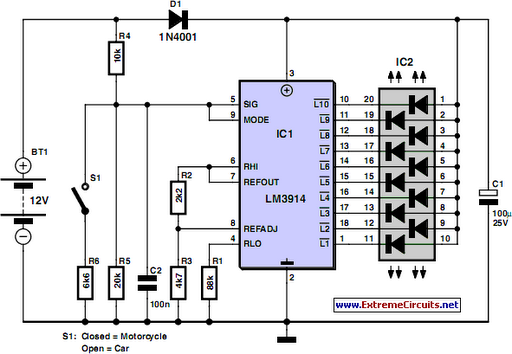
The circuit begins with a power supply connected to either a 12V or 6V battery, selected via switch S1. The LM3914 IC serves as the central component for voltage monitoring, configured in bargraph mode to provide a visual representation of the battery's state. The input voltage from the battery is fed into the LM3914, which interprets the voltage level and activates the corresponding number of LEDs on the bargraph display.
The series diode D1 is crucial as it prevents any reverse polarity that could damage the LM3914, ensuring the reliability of the circuit. The LED readout is designed to light up progressively, with the topmost LED indicating a fully charged state, while the bottom LED serves as a warning that the battery requires immediate charging.
For enhanced visibility and user-friendliness, the circuit can be modified to utilize a color-coded LED display. This alternative approach would allow for a more intuitive understanding of the battery's charge level, with different colors representing various states of charge.
Overall, this circuit is an essential tool for camping enthusiasts and travelers, providing a straightforward method to ensure that batteries remain within optimal operational parameters, thus enhancing the overall experience during outdoor activities.Going camping nowadays involves taking lots of electronic equipment whether for day to day running or for fun and entertainment. Most of the time a charged lead acid battery and a power inverter would be used to ensure a smoothly organized holiday where ideally the missus and the children cheerfully use their electric and electronic gear!
With rec hargeable lead-acid batteries it`s invariably useful - if not essential - to determine whether the power source you`re hauling along on your travels is losing capacity and needs to be topped up. The same circuit would also come in handy when going on a car or motorbike trip as it can check the status of a 12 V (car) or a 6 V (motorcycle) battery.
Although the circuit draws so little power that it will not noticeably load the battery under test, it should not be left connected permanently. The circuit employs the familiar LM3914 (IC1) to display the voltage level. The LED readout creates a battery status readout: when the top LED lights, the battery is fully charged.
When the bottom LED lights, the battery needs imminent charging! Switch S1 selects between 12 V and 6 V operation. A series diode, D1, protects the bargraph driver from reverse supply voltage. A color-coded display with individual LEDs could be used instead of the common-anode bargraph display for better indication of the state of the battery. 🔗 External reference
Related Circuits
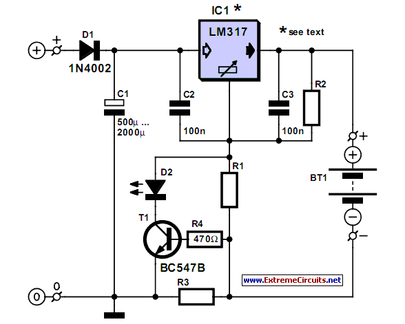
A simple NiCd charger can be constructed using readily available components and an economical LM317 or 78xx voltage regulator. The design incorporates a current limiter made up of resistor R3. The proposed NiCd charger circuit utilizes an LM317 or a...
This small transistor tester employs a simple visual indication system to perform a quick go/no-go check on both NPN and PNP transistors. If the tested device is a functional NPN transistor, the green LED (D1) will flash, while the...
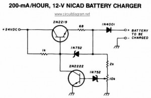
This NiCAD battery charger circuit charges the battery at 75 mA until it is fully charged, after which it reduces the current to a trickle rate. It can completely recharge a dead or unpowered battery in 4 hours, and...

This is a simple and low-cost NiCd and NiMH battery charger. The schematic diagram indicates that the charging current (I) should be set to 1/10 of the battery's rated capacity. For instance, if the battery has a rated capacity...
This automatic NiCd charger for 9V NiCd batteries utilizes the properties of a 555 timer and is straightforward to construct. The design allows for continuous charging of the battery without the risk of overcharging or discharging. With the specified...
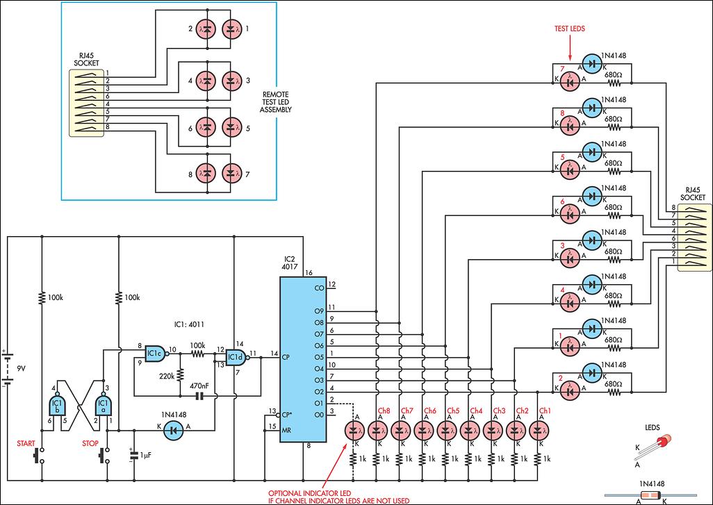
This circuit was developed to fulfill the requirement for a simple network tester that can be operated by a single individual. Previous commercial units necessitated the presence of a person at the other end to observe the remote LEDs,...