
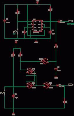
DC relay circuits to delay the release of a second
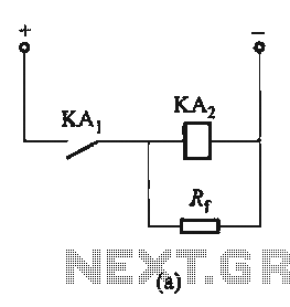
The relay circuit described involves a relay coil that is critical for controlling larger loads with a smaller control signal. The inclusion of a resistor (Rf) or an auxiliary diode (VD) serves to manage the current flow and protect the circuit from back EMF generated when the relay is deactivated. When the relay coil is energized, the magnetic field builds up, allowing the relay contacts to close and complete the circuit for the load.
If a resistor Rf is used in parallel with the coil, it provides a path for the current to continue flowing even after the control signal is removed, thereby prolonging the magnetic field and allowing for a slower release of the relay contacts. This can be beneficial in applications where a quick drop in power could cause issues, such as in motor control or in systems requiring a gradual disengagement.
On the other hand, when an auxiliary diode (VD) is employed, it serves as a flyback diode. This diode allows the current generated by the collapsing magnetic field to safely dissipate, protecting the circuit components from voltage spikes that could otherwise cause damage. The absence of Rf in Figure 6-24(b) indicates a direct connection of the relay coil to the control signal, which may result in a more immediate release of the relay contacts when the control signal is removed.
In summary, the choice between using a resistor or a diode in parallel with a relay coil significantly influences the behavior of the relay in terms of release time and circuit protection. Proper selection based on the specific application requirements is essential for reliable circuit operation.Circuit shown in Figure 6-24. Both ends of the relay coil ' in parallel with a resistor Rf or auxiliary diode VD, is equivalent to power after a short circuit coil core increase, thus making prolonged release. Figure 6-24 (b) of Rf can not.
Related Circuits
The UCD90124/A is utilized to monitor multiple voltages, some of which exceed 2.5V. Scaling circuits are implemented to prevent exceeding the 2.5V maximum on the MON inputs. The inquiry pertains to whether raw voltage values or scaled values should...
The circuit operates without a base current for the transistor. It turns off when the metal sheet is touched, causing the capacitor to start charging. The capacitor charges to 2V over a specified time. The circuit generates a conduction...
A circuit that activates a relay upon detecting audio pulses from one channel of an MP3 player. The intention is to synchronize recorded audio pulses with music to control a motor for mouth movement. For a stereo player, music...
This circuit is a simple -5V power supply using a 555 timer, designed for low-power analog applications involving FET operational amplifiers. The circuit converts +5V to -5V to create a dual power supply. It operates as a 555 astable...
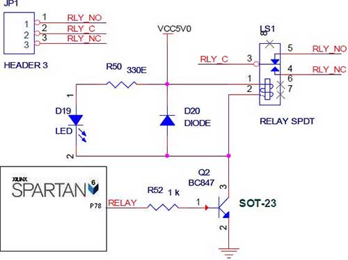
The Spartan-6 board features onboard 5V relay interfacing, as illustrated in the accompanying figure. The ULN2803 serves as a driver for the FPGA I/O lines, with the driver's outputs connected to the relay modules. A PTB connector is provided...
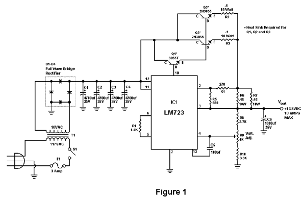
Activated this and inadvertently destroyed several 2N3055 transistors by shorting the emitters to ground. In all cases, the transistors opened up, and no damage to the emitter occurred in any transistor. The alternative circuit in Figure 2 will provide...