
Monitoring Voltages with Scaling Circuits
The UCD90124/A and UCD90120A are advanced power management devices capable of monitoring multiple voltage rails and providing fault detection for over-voltage and under-voltage conditions. When implementing these devices, it is crucial to ensure that all monitored voltages are within the acceptable input range of the MON pins, typically limited to 2.5V. To achieve this, voltage scaling circuits, such as resistor dividers, are employed to reduce higher voltages to safe levels.
For configuring the UCD90124/A in the Fusion software, it is essential to input the actual raw voltage values of the monitored rails. The software allows for the adjustment of gain and offset parameters in the "Other Config" tab, ensuring that the monitoring system accurately reflects the desired voltage levels. For instance, if a voltage divider is used to scale down a 12V rail to a lower voltage that the UCD can handle, the scaling factor must be calculated correctly. The scaling factor is defined as the ratio of the output voltage from the divider to the input voltage being monitored. In the case of a voltage divider producing 1.26V from a 12V rail, the software expects the scaling factor to be expressed as a fraction, contrary to the intuitive understanding of scaling.
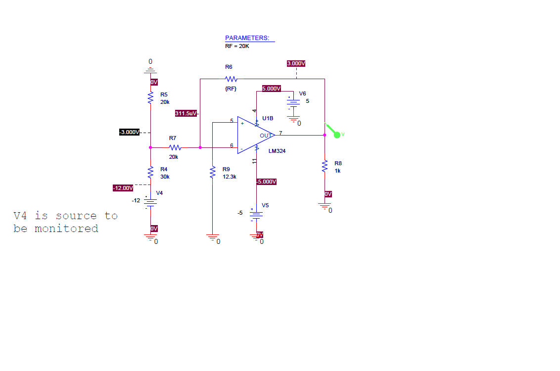
In scenarios involving negative voltage rails, such as a -5.2V rail, an inverting operational amplifier can be employed to convert the negative voltage to a positive value suitable for monitoring. This configuration allows the UCD90120A to accurately read the voltage while ensuring that the input remains within safe limits.
When monitoring multiple rails with different scaling requirements, such as a direct connection for a 1V rail and a divided connection for a 12V rail, it is important to ensure that the scaling factors are set appropriately for each rail. The Fusion software may only provide a single scaling entry, but careful management of the configuration settings can allow for accurate monitoring without compromising the integrity of the measurements.
The operation of these devices and the configuration in Fusion requires a clear understanding of the scaling principles and the electrical characteristics of the components involved. Proper setup ensures reliable monitoring and fault detection, contributing to the overall stability and performance of the power management system.I am using the UCD90124/A, among other things, to monitor multiple voltages. Several of these are > 2. 5v so I have scaling circuits so as not to violate the 2. 5v max on the Mon inputs. My question is, do I enter the raw voltage values in Fusion for such things as over/under voltage fault/warning or do I use the scaled values Are there provisions within Fusion to enter the scaling factors Enter the actual raw values into Fusion. You then set the "gain" and "offset" values in Fusion on the "Other Config" tab. For example, if your external voltage divider is a divide by 2 (0. 5), then you enter 0. 5 for Vout Scale Monitor on the other config tab for the subject rail. I have a question on the setting up "Vout scale monitor" and "Vout Cal monitor". I am monitoring a -5. 2V power rail with UCD90120A device. The Vin to UCD90120A is scaled down with 6. 04K and 8. 25K resistors (other end of the divider tied with +12V). How do I monitor the setting up the scale parameters on this scanario My first suggestion would be using an inverting Op amp between the negative rail and the UCD so that the monitoring input to the MON pin of the sequencer would be the Op amp output which is a positive voltage. I have the same question as the original post but I will elaborate more I have a 12v rail and a 1v rail I want to feed the 1v rail directly into the ADC and the 12v rail divided down.
How do I enter in the scaling for EACH rail (no scaling on 1v rail and 1/6 scaling on the 12v rail). I only see one scale entry. Surely you dont want me to divide the 1v rail down to 1/6 as well All my thresholds will be in the noise. 2. Now click on the `Other Config` tab, and scroll down to the "Scaling" section. The "Vout Scale Monitor" is the scaling factor that will be applied to the rail you selected in step 1.
BTW the scaling factor is completely opposite of how I think of a scaling factor. For example to monitor a 12V rail. I used a 34K and 4K resistor divider. This produces a 1. 26V at the ADC. I expected the scaling factor to be 12. 0/1. 26 or 9. 5, but the software expects 1/9. 5 or 0. 105. All content and materials on this site are provided "as is". TI and its respective suppliers and providers of content make no representations about the suitability of these materials for any purpose and disclaim all warranties and conditions with regard to these materials, including but not limited to all implied warranties and conditions of merchantability, fitness for a particular purpose, title and non-infringement of any third party intellectual property right. TI and its respective suppliers and providers of content make no representations about the suitability of these materials for any purpose and disclaim all warranties and conditions with respect to these materials.
No license, either express or implied, by estoppel or otherwise, is granted by TI. Use of the information on this site may require a license from a third party, or a license from TI. Content on this site may contain or be subject to specific guidelines or limitations on use. All postings and use of the content on this site are subject to the Terms of Use of the site; third parties using this content agree to abide by any limitations or guidelines and to comply with the Terms of Use of this site. TI, its suppliers and providers of content reserve the right to make corrections, deletions, modifications, enhancements, improvements and other changes to the content and materials, its products, programs and services at any time or to move or discontinue any content, products, programs, or services without notice.
🔗 External reference
Related Circuits
These two projects, Wah and Fuzz, are the results of a modification to a Morley dual channel volume control pedal that one of my sons suggested I undertake as he had no use for the volume unit but thought...
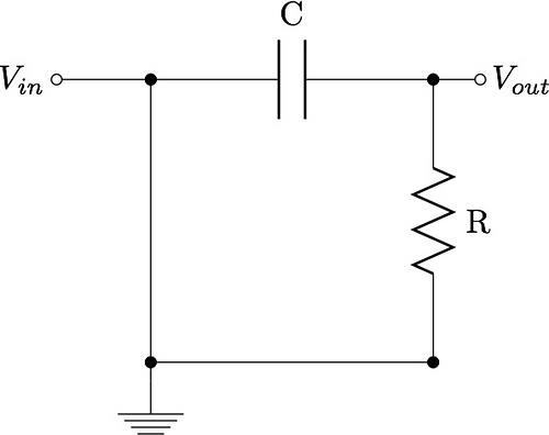
This guide aims to demonstrate the construction of various filter circuits, specifically low pass and high pass filters, along with additional details. The construction of filter circuits is essential in many electronic applications, as they allow for the selective passage...
A 1200 Watt lamp dimmer circuit is designed to control lighting levels and is capable of managing up to 1200 Watts. This circuit utilizes the Q4015LT, which combines a Diac and a Triac for 230V dimming applications. It serves...
These circuits could be used as the basis for Model Railroad DCC Boosters or PWM motor controllers. The first schematic is for a basic 3 Amp - DCC Booster using the LMD 18200 CMOS, H-Bridge. Included in the design...
Many applications require low-frequency signal generators that can deliver high-performance, high-resolution signals. This design idea presents a circuit that generates frequencies from 0 to 1 MHz, providing sinusoidal, triangular, and square-wave outputs with frequency resolution better than 0. A...
The circuit below illustrates powering one or two LEDs from the 120-volt AC line using a capacitor to drop the voltage and a small resistor to limit the inrush current. Since the capacitor must pass current in both directions,...