
DC Servo MOSFET Amplifier
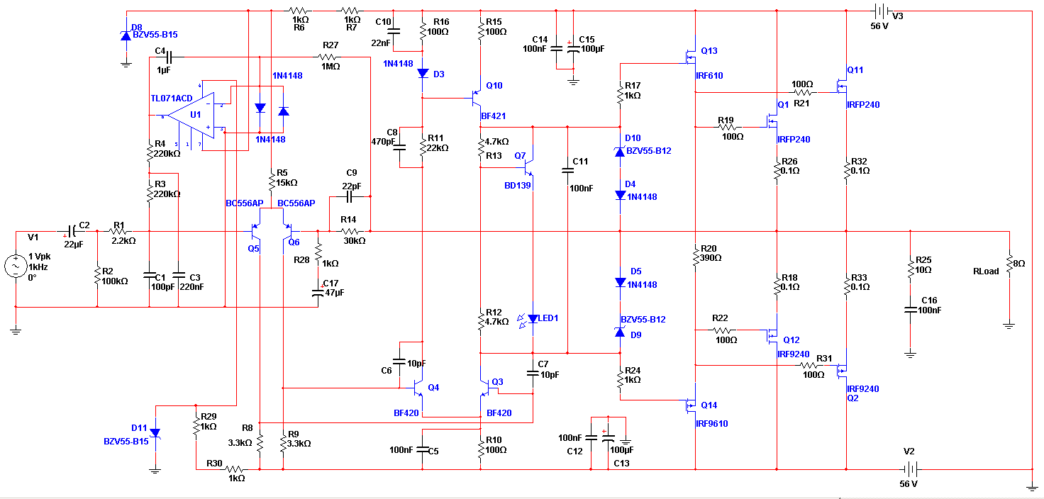
The Apex amplifier circuit is designed to deliver high-fidelity audio amplification. The schematic incorporates a variety of resistor values for R14, allowing for tuning of the amplifier's response and performance. The choice of resistor value affects the gain, bandwidth, and overall stability of the amplifier.
In the circuit, R14 plays a crucial role in determining the feedback network's characteristics, which directly influences the amplifier's linearity and distortion levels. By experimenting with resistor values of 22k, 30k, and 56k, users can observe how these changes impact the amplifier's output characteristics, such as frequency response and gain.
The power supply configuration is another critical aspect of the amplifier's design. Different supply voltages can significantly alter the performance, affecting parameters like headroom, dynamic range, and maximum output power. It is essential to ensure that the power supply meets the voltage and current specifications required by the amplifier to avoid issues like clipping or thermal overload.
When constructing the Apex amplifier, careful attention should be paid to the layout of the circuit to minimize noise and interference. Proper grounding techniques and the use of decoupling capacitors can further enhance the performance of the amplifier. Overall, the flexibility in resistor values and supply configurations allows for a customized approach to achieving the desired audio quality.Apex seems i begin to love this amp the corrected clear schematic is this with different R14 values(tried 22k,30k,56k) and different supply.. 🔗 External reference
Related Circuits
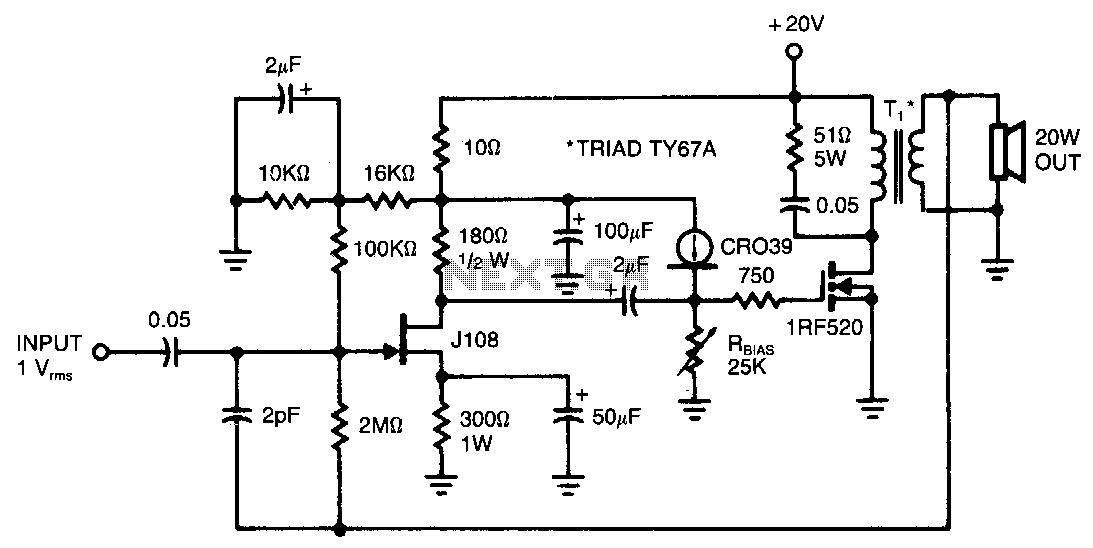
This amplifier provides 20 W of power to an 8-ohm load utilizing a single IRF520 transistor driving a transformer-coupled output stage. The design resembles the audio output stages commonly found in many low-cost radios and phonographs. Distortion remains below...
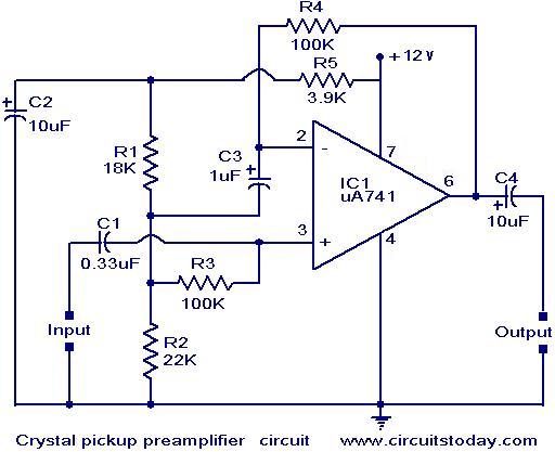
A preamplifier that operates on a single supply and is suitable for high-impedance crystal pickups is presented here. The circuit functions as a non-inverting AC amplifier, with the gain determined by the feedback resistor R4; a smaller R4 results...
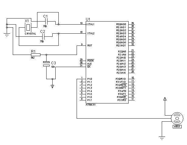
The control signals for the motor's rotation are generated by an 8051 microcontroller. For foundational concepts and information about a servo motor, refer to the article on Servo Motors. The source code utilized is based on the AT89S51 microcontroller....
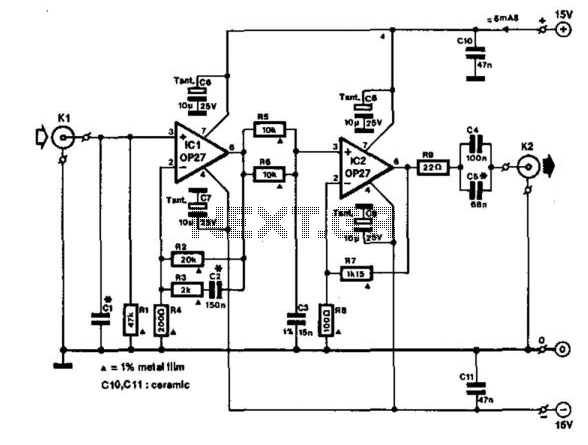
This circuit is mainly intended to provide common home stereo amplifiers with a microphone input. Using a stereo microphone the circuit must be doubled. In this case, two separate level controls are better than a dual-ganged stereo potentiometer. Low...
This amplifier is designed to be integrated with preamplifiers that lack a phono input. A phono input is essential for standard record players equipped with dynamic pick-ups, which remain widely used. The amplifier not only elevates the output of...
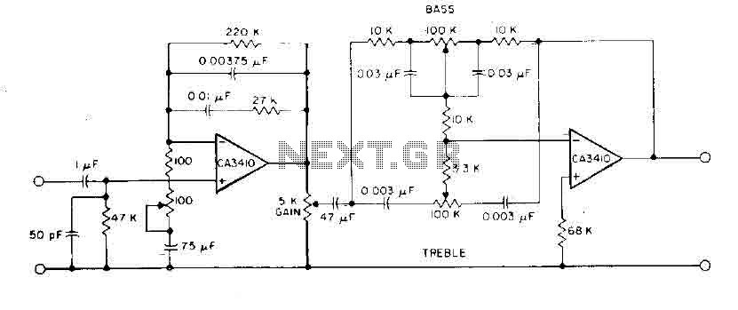
This circuit incorporates RIAA equalization, tone controls, and sufficient gain to drive most commercial power amplifiers using the CA3410 op-amp BiMOS. The total harmonic distortion is minimized to less than 0.035% for an output of 6 V within the...