
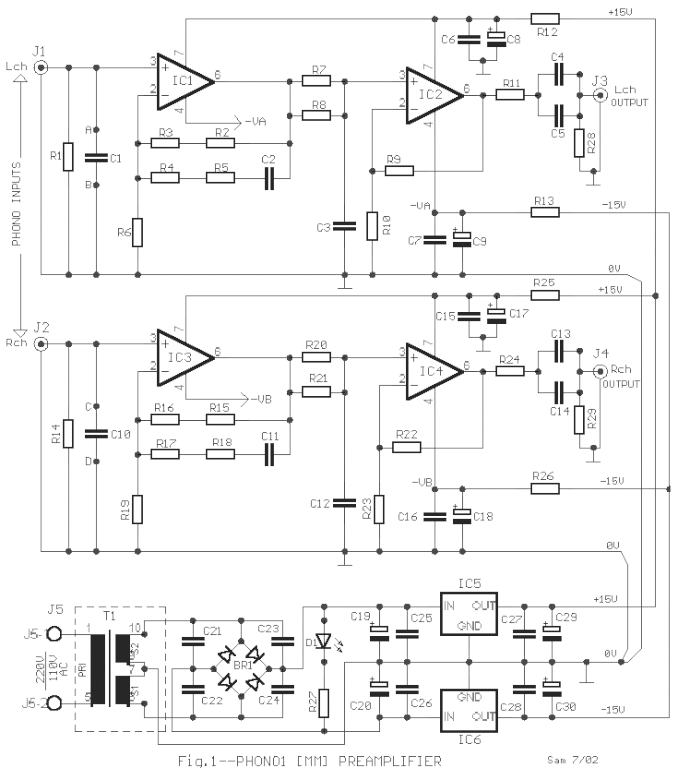
Preamplifier For Magnetic Phono Cartridges
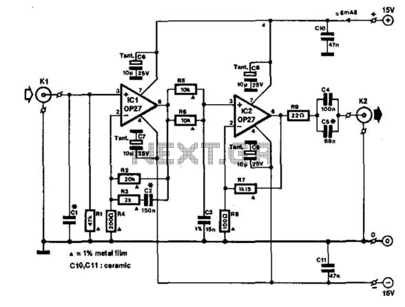
The described amplifier circuit serves as an essential component for enhancing audio fidelity in record playback systems. Its design includes a feedback mechanism that utilizes operational amplifiers to achieve the desired gain and frequency response adjustments. The choice of components, such as polystyrene capacitors for their low distortion characteristics and specific resistor values to minimize noise, is critical in maintaining audio quality. The high-pass filter formed by the output capacitors and the preamplifier input impedance is particularly important for removing unwanted low-frequency artifacts, ensuring that the audio output remains clear and focused.
The power supply considerations are equally significant, as any electromagnetic interference can lead to audible hum in the audio output. Therefore, careful attention must be paid to the transformer selection and the overall layout of the circuit within the enclosure. Proper shielding and grounding techniques should be employed to optimize performance, especially in environments where electronic noise is prevalent. This amplifier circuit, with its adherence to RIAA standards and thoughtful design choices, is well-suited for integration into modern audio systems that aim to preserve the authenticity and quality of vinyl record playback. This amplifier is intended to be added to preamplifiers that have no phono input. Such a phono i nput is required for normal record players with a dynamic pick-up, of which millions are still around. Moreover, the amplifier does not only bring the output of the pick-up to line level, it also adds the correction to the frequency response (according to RIAA requirements).
When recording gramophone records, the frequency characteristic is lifted at the high end. This lift must be countered in the playback (pre)amplifier. The corrections to the frequency response characteristic are according to a norm set by the Record Industries Association of America (RIAA) and also by the IEC. The corrective curve provided by the amplifier is shown in the graph (bold line). The thin line shows the ideal corrective curve. The sharp bends in this at 50 and 500 Hz are nearly obtained in the practical curve by network R3/C2; just above 2 kHz is approached in practice by filter R5/R6/C3.
The arrangement of R3/C2 in the feedback loop of IC1 gives noticeably better results than the usual (passive) filter approach. Circuit IC1 provides a dc amplification of 40 dB, which drops to about 20 dB when the frequency rises above 500 Hz.
To minimize the (resistor) noise and the load of the op amp at higher frequencies, the value of R3 is a compromise. The associated polystyrene capacitor, C2, should have a tolerance of 1 to 2%. To raise the 2-mV output of the dynamic pick-up to line level at 1 kHz, linear amplifier IC2 has been added.
This stage has a gain of 22 dB, so a signal of 250 mV is available at its output. Capacitors C4/C5 at the output, in conjunction with the input impedance of the following preamplifier, form a high-pass filter with a cut-off frequency of 20 Hz; this serves to suppress any rumble or other low frequency noise. The value of CI is normally given in the instruction booklet of the dynamic pick-up. The power supply for the amplifier must be of good quality. Particularly, the transformer should be class A1 with a small stray magnetic field. When the amplifier is built into the record player (best), the power supply should not be included unless it is very well screened; otherwise, hum is unavoidable.
🔗 External reference
Related Circuits
A fundamental component for audio applications, this circuit functions as a general-purpose preamplifier. It is recommended to utilize two circuits for stereo configurations. This audio preamplifier circuit is designed to amplify low-level audio signals, making it suitable for a variety...
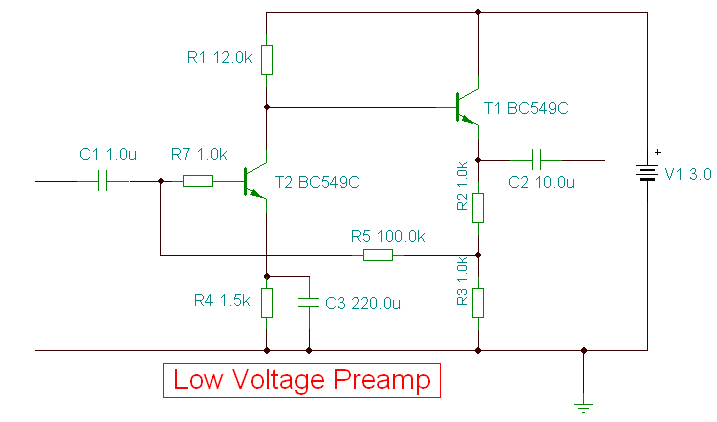
This is a specialized low-voltage version of an audio preamplifier. The emitter voltage of transistor T1 is biased close to half the supply voltage (1.5V) to enable maximum output voltage swing. Both transistors are directly coupled and utilize closed-loop...
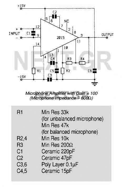
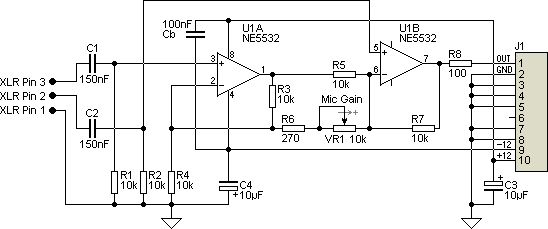
An ultra low noise audio preamplifier particularly suited to microphone preamplification including balanced microphones. The IC features wide bandwidth, low distortion only 0.007% at a gain of 100, and very low noise only 1.3nV/Hz for source impedance up to...
This project originated from a design requirement for a client, specifically for a microphone preamplifier intended for basic public address (PA) systems. The simplicity of this circuit makes it suitable for various applications where a mic preamp is needed,...
The circuit was designed according to the RIAA implementation of a Hi-Fi phono preamplifier for the purpose of reproducing audio from a moving magnet cartridge. The RIAA (Recording Industry Association of America) equalization curve is essential for the accurate playback...
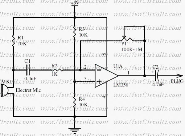
This circuit will be useful if you have an electret microphone that produces a low audio (sound) level and you want to connect it to an amplifier or something like it. The circuit boosts the microphone output voltage to...