
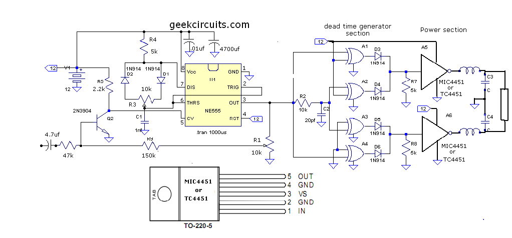
Dc to Dc converter using 555 Timer IC
The first timer is configured to supply a rectangular signal of about 2 Hz at pin 9. The lamp is switched on and off by way of power transistor. The second 555 is configured to supply a square wave at pin 5 that drives the loudspeaker. The loudspeaker of the siren must have a value between 8 and 32 ohms. Using electronic diagram below can be made a very simple water softener. This 555 timer circuit water softener is based on a theory that says that an electromagnetic field or electrical cause small crystals of calcium carbonate in water to join together, forming larger crystals. The circuit below illustrates using a 10x10 matrix to sequence up to 100 LEDs with just three ICs and 20 transistors.
The two 4017 decade counters control the 10 rows and 10 columns so that one LED is selected depending on the output of the decade counters. For example, to expand the circuit to 60 LEDs for displaying minutes or seconds of a clock, the rows counter could be reset from pin 12 (carry out) rather than pin 1 as shown, and the columns counter will be reset from pin 5 rather than pin 1 as shown.
And then add transistors to pins 1, 5, 6, 9, and 11 of the rows counter and pin 1 of the columns counter. Take a look at the "10 Stage LED Sequencer" for a listing of all the connections of the 4017 decade counter.
This is a programmable clock timer circuit that uses individual LEDs to indicate hours and minutes. 12 LEDs can be arranged in a circle to represent the 12 hours of a clock face and an additional 12 LEDs can be arranged in an outer circle to indicate 5 minute intervals within the hour. 4 additional LEDs are used to indicate 1 to 4 minutes of time within each 5 minute interval. The circuit is powered from a small 12. 6 volt center tapped line transformer and the 60 cycle line frequency is used for the time base. The transformer is connected in a full wave, center tapped configuration which produces about 8. 5 volts unregulated DC. A 47 ohm resistor and 5. 1 volt, 1 watt zener regulate the supply for the 74HCT circuits. A 14 stage 74HCT4020 binary counter and two NAND gates are used to divide the line frequency by 3600 producing a one minute pulse which is used to reset the counter and advance the 4017 decade counter.
The decade counter counts the minutes from 0 to 4 and resets on the fifth count or every 5 minutes which advances one section of a dual 4 bit binary counter (74HCT393). The 4 bits of this counter are then decoded into one of 12 outputs by two 74HCT138 (3 line to 8 line) decoder circuits.
The most significant bit is used in conjunction with an inverter to select the appropriate decoder. During the first eight counts, the low state of the MSB is inverted to supply a high level to enable the decoder that drives the first 8 LEDs. During counts 9 to 12, the MSB will be high and will select the decoder that drives the remaining 4 LEDs while disabling the other decoder.
The decoded outputs are low when selected and the 12 LEDs are connected common anode with a 330 ohm current limiting resistor to the +5 volt supply. The 5th output of the second decoder (pin 11) is used to reset the binary counter so that it counts to 11 and then resets to zero on the 12th count.
A high reset level is required for the 393 counters, so the low output from the last decoder stage (pin 11) is inverted with one section of a 74HCT14 hex Schmitt trigger inverter circuit. A 10K resistor and 0. 1uF cap are used to extend the reset time, ensuring the counter receives a reset signal which is much longer than the minimum time required.
The reset signal is also connected to the clock input (pin 13) of the second 4 bit counter (1/2 74HCT393) which advances the hour LEDs and resets on the 12th hour in a similar manner. Setting the correct time is accomplished with two manual push buttons which feed the Q4 stage (pin 7) of the 4020 counter to the minute and hour reset circuits which advance the counters at 3.
75 counts per second. A slower rate can be obtained by using the Q5 or Q6 stages. For test purposes, you can use Q1 (pin 9) which will advance the minutes at 30 per second. The time interval circuit (shown below the clock) consists of a SET/RESET flipflop made from the two remaining NAND gates (74HCT00). The desired time interval is programmed by connecting the anodes of the six diodes labeled start, stop and AM/PM to the appropriate decoder outputs.
For example, to turn the relay on at 7:05AM and turn it off at 8:05AM, you would connect one of the diodes from the start section to the cathode of the LED that represents 7 hours, the second diode to the LED cathode that represents 5 minutes and the third diode to the AM line of the CD4013. The stop time is programmed in the same manner. Two additional push buttons are used to manually open and close the relay. The low start and stop signals at the common cathode connections are capacitively coupled to the NAND gates so that the manual push buttons can override the 5 minute time duration.
That way, you can immediately reset the relay without waiting 5 minutes for the start signal to go away. The two power supply rectifier diodes are 1N400X variety and the switching diodes are 1N914 or 4148s but any general purpose diodes can be used.
0. 1 uF caps (not shown on schematic) may be needed near the power pins of each IC. All parts should be available from Radio Shack with the exception of the 74HCT4017 decade counter which I didn`t see listed. You can use either 74HC or 74HCT parts, the only difference between the two is that the input switching levels of the HCT devices are compatible with worst case TTL logic outputs.
The HC device inputs are set at 50% of Vcc, so they may not work when driven from marginal TTL logic outputs. You can use a regular 4017 in place of the 74HCT4017 but the output current will much lower (less than 1 mA) and 4 additional transistors will be required to drive the LEDs.
Without the buffer transistors, you can use a 10K resistor in place of the 330 and the LEDs will be visible, but very dim. Using the 4017 to drive LEDs with transistor buffers is shown in the "10 Channel LED Sequencer" at the top of In this circuit the 555 timer is used in a novel way, as a voltage controlled switch.
The old and omnipresent NE555 can be very good at something it was not meant for: driving relays or other loads up to 200 mA. The picture shows an example circuit: if the input level rises over 2/3 of the supply voltage it will turn on the relay, and the relay will stay on until the level at the input drops below one third of the supply voltage.
If the relay and D1 were connected between pin 3 and ground, the relay would be activated when the input voltage drops below one third, and deactivated when the input voltage goes over two thirds of the supply voltage. It is also a nice advantage that the input requires only about 1 uA, which is something bipolar transistors can`t compete with.
(This high impedance input must not be left open. ) A large hysteresis makes the circuit immune to noise. The output (pin 3) can only be either high or low (voltage-wise), and it changes its state almost instantenously, regardless of the input signal shape. The voltage drop across the NE555`s output stage (at 35-100 mA) is 0. 3-2. 0 V, depending on the way the relay is connected and the exact current it draws. D1 is absolutely vital to the safety of the integrated circuit. The circuit was designed to produce a circuit that will alarm a sleeping person to prevent snoring by using a vibrator instead of an audio alert so as not to affect the whole household.
It contains a trigger indicator, peak display indicator, a level control and a variable trigger threshold. A small motor enclosed in a film case with of 35 mm in size, will provide the vibration and suitably positioned under the pillow or mattress.
The operation of the alarm is depends on several adjustments of the components. The variable resistor VR2 will designate the preset period of triggering the alarm while variable resistor VR1 controls the volume of the snore. The threshold control will set the triggering of the alarm since a snore is a continuous sound lasting for several seconds.
It has a set delay so it will not activate with short noises such as car horns, doors slamming, and others. As the circuit gets activated, the vibrations will work gently to wake the snorer or force him to change his sleep posture.
To illustrate the scenario in general, the circuit may be divided into four partitions, according to the sequence of operation, using a low pass filter, precision rectifier, delay-on circuit, and timer and motor drive. An electrets condenser microphone functions as the input transducer to the amplifier and low pass filter around the op-amp circuit of IC1 to filter out high frequency noises by reducing the amplitude of frequencies higher than the frequency response limit of the system.
It will only allow the passage of low frequencies. The precision rectifier made by op-amp IC2 converts the amplified sound to DC which will be filtered again. This should go on for a few seconds so the delay circuit will be activated. Op-amp IC3 comprises the delay circuit and will function as a level shifter by comparing the reference input set by the threshold control VR2 to the charge on capacitor C8.
The timer and motor drive will be triggered upon reaching the threshold. The potentiometer R15 can be made to adjust the delay of the motor to start running. To illustrate the operation of the circuit in detail, it starts as the sound is received by theECMmicrophone followed by amplification from the op-amp IC1, reducing high frequency gain and acting as an active low pass filter. It is possible to utilize a dynamic microphone with the elimination of resistor R1. The gain at low frequencies is inversely proportional as frequencies rise above 1 kHz and the level is controlled by VR1.
The conversion of audio signal happens in op-amp IC2 as it functions as a precision rectifier to boost the signal levels by having a gain ratio of R7/R6. The feedback loop contains the diode 1N4148 that is accountable for producing a positive rectified signal from the conversion of audio signal.
The non-inverting inputs of op-amps IC1 and IC2 is biased by C2, R4 and R5 to half the supply voltage. The visual indication of peak levels will be supplied by LED1 by showing a flash instead of continuous illumination.
These peak signals are fed by R8 and C5 to the LED1. The flashing of LED1 by each snore is modified by VR1. The delay is crucial to the circuit so that the alarm will not be triggered with any form of background noise. It will only be triggered after the snoring is started. The need for an input delay is important so the alarm will not set off in the middle of the night with a car door opening or a car horn.
The alarm employs high frequency roll-off so as not to get affected by other sound with fundamental frequencies or harmonics. C8 and R12 provide the input delay. Capacitor C8 has a value of 33 uF as an electrolyte capacitor. It will start to charge slowly when using the half wave rectified signal from IC2. Without any signal, C8 will not charge and will discharge via R11 and R12. The combination of R9, R10 and D2 provides further rectification of the input signal and causing 1N4148 diode D2 to conduct with a little forward bias.
This will also cause C8 to pre-charge even without a signal. Since op-amp IC3 functions as a variable level detector, it also provides the delay while the threshold is controlled by VR2 for the capacitor C8 to have a voltage charge equal to the pin 3 of the op-amp. With this event, LED2 will indicate the triggering of the circuit which will cause the normally high IC3 to change to low output.
The charging of the capacitor can be computed only when a fixed DC current is used but will not be possible on this circuit since the intermittent snore provides the charging current. The delay circuit output is normally high on during the triggering stage and will change shortly when the prolonged snore is being identified.
The change will trigger IC4 555 timer because of the correct polarity as the IC functions in monostable mode. A delay of 24. 2 seconds can be obtained from the values of C9 and R15. Loads of up to 200 mA can be driven by the 555 timer output while transistors Q1 and Q2 can source up to 3 A.
The power dissipated on the load and will not require heatsinks when both transistors are ON. During the construction of the circuit some key points should be considered. A motor with high power and high torque should not be used. Similarly, the motor must not exceed 1 A of current from the power supply. However, a 9 V or 12 V electric motor is preferred. A resistor can be added in series with the motor if it is producing excessive vibration. Using a multimeter while the motor is running can measure the value of the DC current. If the motor would draw a current less than 200 mA, as supplied by the 555 timer, then it won`t be necessity for R16, Q1 and Q2. Short flashes are produced by LED1 to indicate the peak detection of the sound. This detection can be adjusted by VR1 which will charge capacitor C8 slowly. The threshold to allow the circuit to trigger after a few seconds is adjusted by VR2. This triggering is indicated by LED2. The capacitor C8 will start to decompose during the interval between snores. Because of this, the circuit will not give false alarm with any surge of short noise. Snoring can be caused by a lot of factors and reasons the can be out of our control such as allergies, asthma, a cold, sinus infections, being male, being middle aged or beyond, or hereditary.
It can also be within our control such as sleeping posture, alcohol or medications, a history of smoking, and being out of shape or overweight. The blockage in irregular flow of air may be due to obstruction in the nasal passageway, fat gathering in and around the throat, mispositioned jaw due to tension in the muscle, and throat weakness which causes the throat to close during sleep.
Despite of this snore alarm circuit, there are still natural ways of preventing or reducing the snoring like losing weight, clearing the nasal passages, avoiding certain foods, medications and alcohol before bed, elevating the head of the bed, and sleeping on your side. A circuit similar to this can also detect if an infant sleeps on his back. 🔗 External reference
Related Circuits
I had a Basic Stamp project that needed to measure a nominal 12 volt battery, and I wanted a simple solution. This is the simplest I could come up with. The 555 timer will put out positive pulses. The...
Currently, high-power, high-frequency, narrow pulsing applications primarily utilize vacuum tubes, such as secondary electron transmitting tubes, discharge gap switches, trigatrons, and hydrogen brake pipes. The main research focus is on improving the switching speed of these vacuum devices, aiming...

This is an ADP1821 step-down DC-to-DC converter circuit. This circuit utilizes the ADP1821, which is a synchronous pulse-width-modulated (PWM) step-down controller. The ADP1821 is designed to efficiently convert a higher input voltage to a lower output voltage while maintaining high...
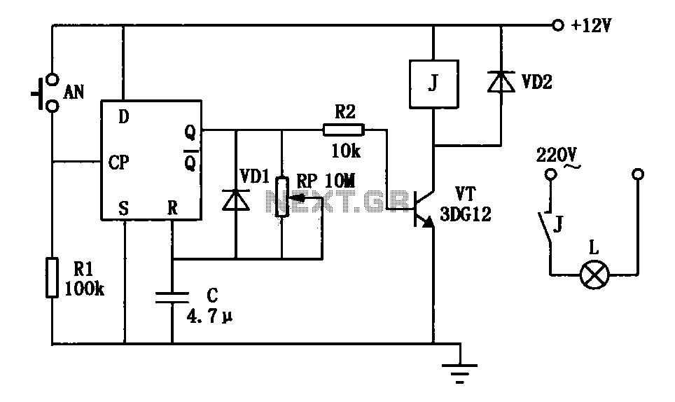
An exposure timer circuit is illustrated using D flip-flops, allowing for timing adjustments between 1 to 30 seconds. The D flip-flop circuit is connected to a one-shot timer. When exposure is required, pressing button AN generates a pulse that...
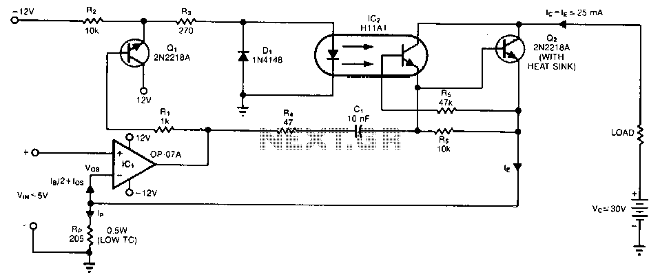
A single programming resistor (Rp) provides an output current range of approximately six decades. It is important to note that the temperature coefficient (TC) of this resistor can introduce potential errors, as it dissipates 125 mW when the junction...
This document presents an improvised circuit model designed to eliminate unwanted DC offset voltage from the output, which affects previously discussed circuits. All prior circuits were intended as low-power Class D amplifier sources suitable for driving headphones through a...