
Several questions and countermeasures in the high-pressure frequency converter is employed

An adjustable high-voltage DC generator utilizes the intersection of mains frequency and alternating current as its power source. An undervoltage and part-commutation inverter circuit generates undervoltage pulses, which are then boosted by a voltage transformer to produce high-pressure pulses. This is controlled by a rectifier that converts it into high-voltage direct current. The pulse generator structure of the adjustable high-voltage DC is depicted in Figure 1. The high-pressure pulse generation involves sending the high-voltage direct current from the power supply into a controllable switching element to produce the desired high-pressure pulse.
The reverse control and driving section operates under high pressure, managing the opening and closing of the switching element. The SG3525 chip is employed based on a PWM control method for this purpose. In the driving circuit, a Mitsubishi IGBT is used to drive the M57962L chip. Initially, the alternating current from the mains frequency is commutated, and a half-controlled bridge rectifier circuit is selected, utilizing a bidirectional thyristor (BTA20) as the switching element. The mean voltage value formula for the single-phase half-controlled bridge rectifier circuit is given in formula 1. The control mode is based on phase control, where the opening angle of the thyristor is adjusted to achieve the desired amplitude of the direct current. The control chip selected is the TCA785, a phase control dedicated chip from Siemens. Additionally, a distinguishing circuit is designed for accurate recognition of the zero crossing in the alternating current voltage. The schematic circuit diagram for the undervoltage commutation and control is shown in Figure 2. The inverter circuit topology for undervoltage employs a semi-bridge inverter circuit, utilizing a Metal-Oxide-Semiconductor Field-Effect Transistor (MOSFET) of type IRF840. During the rapid shutdown of the MOSFET, the flywheel diode experiences backward recovery, leading to the generation of very high surge voltage during release and recovery phases.
This comprehensive design addresses the challenges associated with traditional vacuum tube systems, enhancing efficiency and reliability while leveraging modern semiconductor technology to deliver high-performance pulse generation solutions.At present, that utilize in the high-power, high frequency, narrow pulsing application is basically vacuum tubes, for instance: Secondary electron transmitting tube, discharge gap switch, trigatron, hydrogen brake pipe, etc. The main research direction is how to improve the switch speed of the vaccum device of electricity, reduce it to touch off an
d rock, develop it with its high-pressure driving circuit of suitable high speed. But devices such as the vacuum tube, etc loss big, the driving circuit is huge and cooling shortcoming of trouble, etc. ; Meanwhile, in order to protect it fast when the klystron strikes sparks, need to set up complicated crow bar tube and flip flop in the modulator frequently, efficiency and reliability [1 ] of the direct influence modulator of these questions.
In recent years, because voltage and power level of the semiconductor device are promoting constantly, correlation technique is complete progressively too, create conditions for solving the above-mentioned problem. Because of this technological development trend, this text has designed the fast pulse generator of a new kind of high pressure.
Upper voltage, sharp pulse and high repeatability are the developing direction of the pulse power device. High frequency is an effective way of reducing the systematic volume. Originally design adopting igbt as main switching element, it is 5kv to output the peak-to-peak value of pulse voltage, the frequency is adjustable for 1khz- 10khz, the pulse front edge is 200ns.
1 Adjustable high-voltage D. C. generator: We use the intersection of mains frequency and alternating current as power, in the intersection of undervoltage and part commutate and inverter circuit produce the intersection of undervoltage and pulse, passages through which vital energy circulates wash the voltage transformer boost, not passing again as the high-pressure pulse, controlled rectifier is the high voltage direct current. We are supplied to him as high-pressure direct current power supply the final high-pressure pulse generation part.
The pulse generator structure of the adjustable high voltage direct current is shown as in Fig. 1. 2 Some of high-pressure pulse generation: Send the direct current that the high-pressure direct current power supply offers into controllable switching element under high pressure, produce our required high-pressure pulse. 3 Reverse control and driving part under high pressure: Control and reverse openning and shutoff of switching element in the course under high pressure.
We adopt the chip sg3525 based on pwm control method in controlling. In driving circuit, adopt igbt of Mitsubishi Company to drive the chip m57962l specializedly. We commutate the alternating current of mains frequency at first, what the topological structure is chosen is the bridge rectifier circuit of half control, what switching element is chosen is bidirectional thyristor bta20. Single-phase half control bridge rectifier circuit commutates the voltage mean value formula such as formula 1 Show 5]: According to this formula, adopt the control mode of phase place, namely control through the openning angle of the triode thyristor that uses to the undervoltage rectification part, get the adjustable direct-flow undervoltage of the amplitude.
The control chip chooses tca785 phase control special purpose chip of siemens Company. Meanwhile, for the zero of alternating current voltage of accurate recognition, designed the distinguishing circuit of zero. Undervoltage is commutated and controlled the schematic circuit diagram to be shown as in Fig. 2. The inverter circuit topological structure of undervoltage adopts the inverter circuit of the semi-bridge, switching element chooses the electric field effect tube mosfet, the type is irf840.
In the fast shutoff course of mosfet, the backward recovery of fly-wheel diode and very high surge voltage of production in release and subsidiary 🔗 External reference
Related Circuits
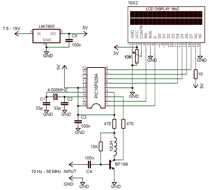
The frequency meter is capable of measuring frequencies ranging from 10 Hz to 60 MHz, with a precision or resolution of 10 Hz. It can be utilized to assess the frequency of various devices such as oscillators, transmitters, frequency...
In the NIXIE clocks constructed, a large mains transformer was avoided within the clock itself by using an AC adapter that connects to the mains wall plug. This necessitated the use of an up-converter to generate the 180V anode...
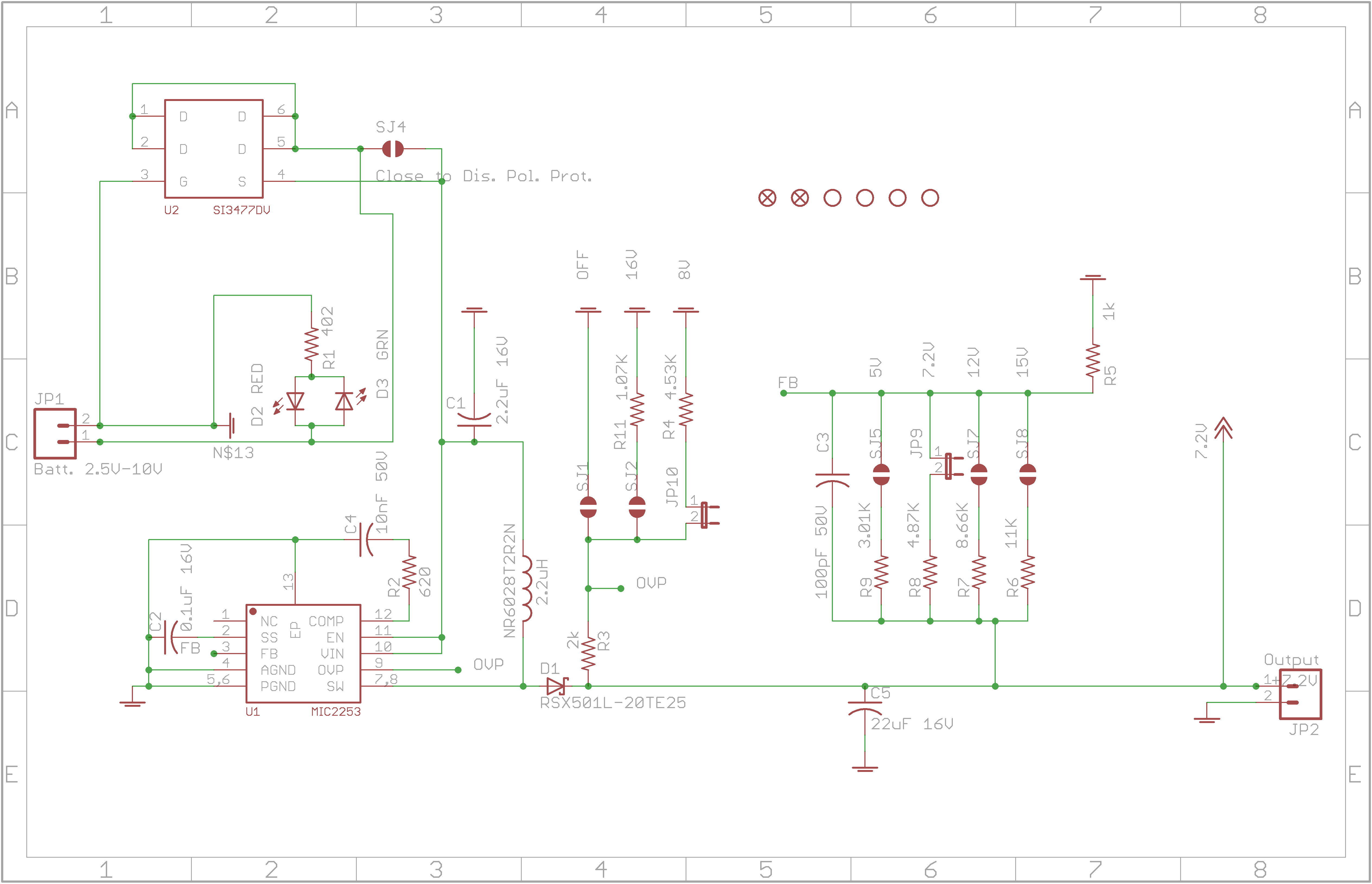
The circuit allows for various combinations of input voltages (Vin) and output voltages (Vout). The current case under debugging involves Vin=3.6V and Vout=7.2V, with a load represented by a 120-ohm resistor. The calculated duty cycle is D=0.5, indicating 50%,...
A standard serial interfacing for PC, RS232C, requires negative logic, i.e., logic 1 is -3V to -12V and logic 0 is +3V to +12V. To convert a TTL logic, say, TxD and RxD pins of the uC chips, thus...
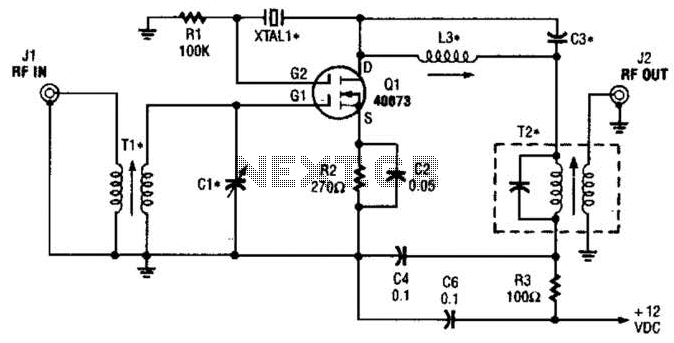
The second gate (G2) of a MOSFET can be utilized to integrate a crystal oscillator within the same stage as a frequency mixer. While this technique is common in tube technology, it is rarely implemented in dual-gate MOSFET circuits....
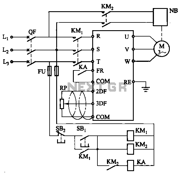
Electromagnetic brake motors consist of a motor and an electromagnetic brake, forming a standard assembly. The circuit diagram is provided. In this configuration, FR represents the forward run and stop command terminal, while the intermediate relay KA is employed...