
Design and simulation study of anti exciting type switching power supply of single-end
PSPICE software, developed by EDA company ORCAD, is a widely recognized circuit simulation tool. Compared to other simulation software, PSPICE presents numerous advantages, including an extensive library of models and components that users can directly access and modify according to real-world requirements. Users can create custom models, enhancing simulation accuracy. PSPICE allows for circuit analysis without the need for physical components, thus eliminating constraints related to component availability and types during emulation. Its user-friendly interface and robust operational capabilities enable users to efficiently simulate complex circuits, thereby reducing the overall design cycle and costs. The software also features a waveform analysis window, facilitating convenient observation and output of waveform characteristics, which is crucial for circuit design.
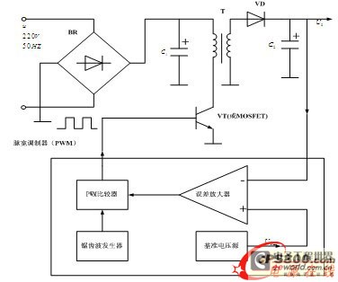
A switching power supply converts AC input, either single-phase or three-phase, into the required DC voltage. The circuit primarily consists of an electromagnetic disturbance smoothing circuit, an input and commutation smoothing circuit, a power inverter, and an output smoothing circuit. The fundamental principle of a switching power supply involves a closed-loop control system comprising a voltage feedback control loop and an inductor current feedback control loop. The current loop enables the input voltage to closely trace the sine wave of the input current, stabilizing the output voltage. The process begins with filtering and commutating the input voltage to obtain the DC voltage U1 through the electrical network. This voltage is then stepped down using a power switch, such as a gas switching tube (VT) or MOSFET, and transformed into a high-frequency square wave by a voltage transformer (T). The output is subsequently processed through a commutation smoothing circuit composed of a diode (VD) and capacitor (C2) to yield the desired high-quality DC voltage UO.
The feedback mechanism utilizes a sense resistor to convert the current flowing through the switching tube into a feedback signal for the voltage, which is then compared with the detected voltage in the control loop. This comparison generates a PWM waveform to regulate the output voltage magnitude. This description focuses on the design of the high-frequency voltage transformer and the control circuit for the anti-exciting single-ended switching power supply. The control method employed is a peak current control scheme, which operates by turning on a fixed clock while shutting off the peak current. This method does not directly manipulate the PWM pulse width based on the voltage error signal but instead indirectly controls the PWM pulse width based on the inductive current peak value.Because switching power supply energy-conservation also brings the huge economic benefits, cause the attention of the various circles of society to be popularized rapidly. With the technical development at full speed of power, high frequency, becoming the development trend of stabilized voltage supply of switch miniaturizedly, integratedly.
Single -end anti exciting type switching power supply not merely has small, the circuit is succinct, advantage that reliability is high with high efficiency, and there is automatic equalization from various places that outputs loaded ability, are often used for designing the accessory power supply of high-frequency switching power supply of high-power or drive power of the power switch [1-2]. PSPICE software is the common circuit analogue simulation software that EDA company ORCAD with most well-known domain developed.
Compared with miscellaneous simulation software, PSPICE has a lot of advantages: Having increased the kinds of model and components and parts, the components and parts in user`s all right direct call model base, also can revise the parameter of the model according to the needs of reality, or set up one`s own model; Use the model set up of PSPICE to be more accurate, the real circuit of simulation that it can be better; Because analyze to the circuit that does not need actual components and parts with PSPICE, so, will not be influenced by quantity and type of the components and parts in emulation; The operation of PSPICE is simpler, practicability is strong, utilizing its user will pay emulation to the complicated circuit, reduce the cycle sum expenses of circuit design. PSPICE has good man-machine interface and control mode, pass the waveform analysis window, users can be convenient to observe and output corrugate properties, have important directive significance on design of the circuit.
Switching power supply ac input Single-phase or three phases The voltage is turned into a device of the required direct-current volts. The circuit is mainly input the smoothing circuit of electromagnetic disturbance, input and commutated the smoothing circuit, inverter of power, exported and commutated the smoothing circuit etc.
to make up. The basic principle of switching power supply is shown as in Fig. 1, the controlling circuit is a piece of one pair of closed loop control systems outputted the control loop of voltage feedback and the inductor current feedback control loop makes up. Among them, the electric current loop can make the change of the input voltage of tracing of input current close to the sine, output of making the voltage stable of the voltage ring.
Its basic principle is: Exchanging the input voltage is filter, commutates and filters and gets the direct-current volts U1 by the electric wire netting, after stepping down through the power gas switching tube VT or MOSFET chopping, high-frequency voltage transformer T, output the required voltage of high-frequency square wave, commutate the smoothing circuit the output composed of VD, C2 finally, receive required high quality, high-quality direct-current volts UO to export. Utilize the sense resistor of electric current to transform the electric current of the gas switching tube into the feedback signal of the voltage, then compare with detected voltage of control loop of the voltage, produce PWM wave, and then control the magnitude of the output voltage.
This text only concentrates on high-frequency voltage transformer and design of the control circuit to the design of the anti exciting type power supply circuit of switch of multi-functional single-end. The control method is as follows, crest current control pattern, it is the control method that a fixed clock is turned on, the crest current shuts off, it does not directly control PWM pulse width with the error signal of the voltage, but use the indirect control PWM pulse width of inductive current of the crest val
🔗 External reference
Related Circuits
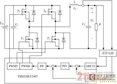
Traditional UPS systems use analog circuit control, which presents significant limitations for both manufacturers and users, regardless of whether they employ technology or SPWM technology. With advancements in information technology, the introduction of high-speed digital signal processing chips, known...
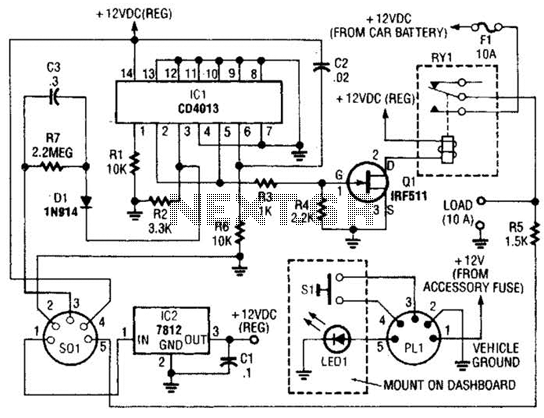
The power controller operates from the vehicle's accessory switch, allowing the load to receive power only when the ignition key is in the "on" position. A momentary pushbutton controls a load of up to 10 A using half of...
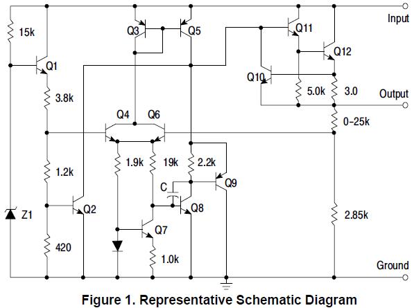
MC78L15ABPG positive voltage regulator, 100mA, TO-92 The MC78L15ABPG is a low-dropout (LDO) voltage regulator designed to provide a stable output voltage of 15V with a maximum output current of 100mA. This device is packaged in a TO-92 form factor, which...
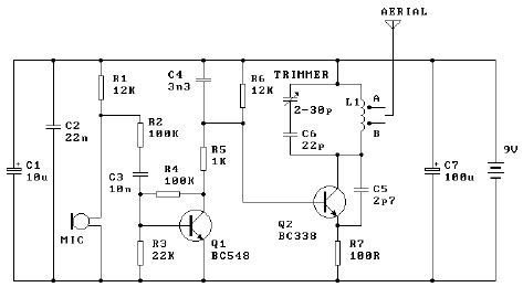
The tuned coil L1 has two output tap points for the antenna connection, labeled "A" and "B." Both outputs are low-level, allowing the user to select between a stable low range or a more unstable but higher range. Tap...
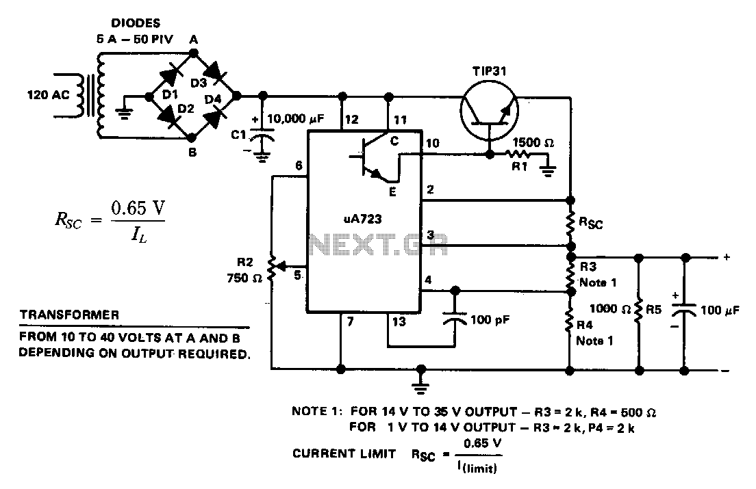
The supply 6-66 can be utilized for output voltages ranging from 1 to 35 V. The line transformer must be selected to provide approximately 1.4 times the desired output voltage from the positive side of filter capacitor C1 to...
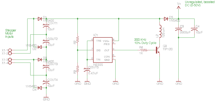
The circuit depicted in the schematic below represents an enhanced generator electronics system. It is an unregulated switcher designed to maximize sound output while ensuring prolonged CPU operation. This circuit efficiently transfers electrical energy from the generator, outperforming traditional...