
diagram shows rather simple voltage

The voltage stabilizer circuit operates by continuously monitoring the output voltage and comparing it to predetermined reference levels using operational amplifiers. When the output voltage deviates from the set thresholds, the op-amps trigger the SSRs, which in turn switch the transformer taps to either increase or decrease the output voltage. This feedback mechanism ensures that the output voltage remains stable despite fluctuations in the input voltage.
The design includes multiple presets (P1 to P7) that allow for fine-tuning of the tripping points, enabling customization for different load requirements and voltage conditions. The SSRs provide a fast switching capability, which is essential for maintaining voltage stability in applications where power demands may vary rapidly. The choice of SSRs also contributes to the overall reliability and efficiency of the circuit, as they can handle high currents with minimal heat generation compared to traditional electromechanical relays.
Additionally, the transformer used in the circuit is equipped with multiple taps, allowing for a range of output voltage levels. The selection of the appropriate tap is determined by the SSRs based on the feedback received from the op-amps. This dynamic adjustment capability is crucial for protecting sensitive electronic equipment from voltage fluctuations that could lead to damage or operational inefficiencies.
Overall, this voltage stabilizer design is well-suited for applications requiring robust power handling and precise voltage regulation, making it an effective solution for a variety of industrial and commercial environments.The diagram shows a rather simple voltage stabilizer design which can hold huge output power in the order of 5 to 10KVA. The use of SSR or solid state relays makes the output stage easy to configure and very accurate - thanks to the modern SSRs which are designed to trigger massive power in response to smaller input DC potentials.
The proposed circuit of a simple 5 KVA to 10 KVA automatic voltage stabilizer circuit is easy to understand. All the opamps are arranged in standard voltage comparator modes. The presets P1 to P7 can be adjusted as per the required tripping points, which will correspond to the output SSR switching and the subsequent transformer tap selections. These TAPs are chosen by the appropriate SSRs in response to the varying AC voltages, thus adjusting the output voltage to the appliances close to normal levels.
🔗 External reference
Related Circuits
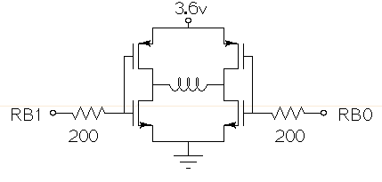
Drive a small (3.6V, <1A) brushed motor bidirectionally with a PIC microcontroller (MCU). The available space is extremely limited, so a single 3.6V power supply will be used for both the motor and the PIC, with minimal drive circuitry required. There is no dedicated motor driver IC that operates at this low voltage, making a discrete H-bridge the most suitable drive arrangement. The NXP PMV30UN and PMV32UP have been identified as suitable N-type and P-type drive MOSFETs. Since both the PIC and the motor share the same power supply, it is questioned whether it is possible to eliminate the usual driving circuitry for an H-bridge and connect the transistors directly to the MCU pins. Potential pitfalls of this approach should also be considered. To design a bidirectional motor drive circuit using a PIC microcontroller and a discrete H-bridge configuration, the following considerations must be taken into account. The H-bridge consists of four MOSFETs arranged in a configuration that allows current to flow through the motor in either direction, enabling bidirectional control. The NXP PMV30UN and PMV32UP MOSFETs are suitable candidates due to their low on-resistance and capability to operate at the required 3.6V supply voltage. The connections between the PIC MCU and the MOSFETs should be made with consideration of the gate drive requirements. Directly connecting the MOSFET gates to the MCU pins can be feasible, but it is essential to ensure that the MCU can provide sufficient gate drive voltage to fully turn on the MOSFETs. A typical threshold voltage for these MOSFETs is around 1V, so the output high level from the PIC should exceed this threshold to ensure efficient operation. It is also critical to incorporate pull-down resistors on the gate pins to prevent the MOSFETs from floating when the MCU is in a high-impedance state. This will help avoid unintended motor activation. Additionally, using gate resistors can help dampen any oscillations and limit inrush current during switching, which could potentially damage the MOSFETs or the MCU. Another consideration is the back EMF generated by the motor when it is switched off or when changing direction. This can induce voltage spikes that may damage the MCU or the MOSFETs. To mitigate this risk, flyback diodes should be placed in parallel with each MOSFET to provide a path for the back EMF, ensuring safe operation of the circuit. Thermal management is also a critical aspect of the design. Although the MOSFETs are rated for low on-resistance, continuous operation near their current limits can lead to significant heat generation. Adequate heat dissipation measures, such as heat sinks or thermal pads, should be considered. In summary, while it is possible to connect the MOSFETs directly to the MCU pins, careful attention must be given to gate drive requirements, protection against back EMF, and thermal management to ensure reliable and efficient operation of the bidirectional motor drive circuit.
The circuit serves as a foundational design, requiring experimentation for specific applications. In popular microwave bands, local oscillators (LOs) are typically generated using overtone crystal oscillators followed by multipliers. A table presents the standard LO frequencies for narrowband segments,...

There are two regulator circuits that utilize the L200 integrated circuit from SGS-Thomson to regulate voltage and current. In circuit Fig. 1, the output voltage can be adjusted using the variable resistor RV1. In Fig. 2, both output voltage...
This door minder electronic project is based on a 555 timer circuit and utilizes an infrared (IR) beam to monitor doorways, passageways, or any other designated area. When the IR beam is interrupted, a relay is activated, which can...

The preamp being discussed features optional tone and balance controls. While these can be omitted if desired, it is generally not recommended. The input switching capability of this preamp can be extended to accommodate additional signal sources if required. However,...
The circuit shown above can be used to control a unipolar stepper motor which has FOUR coils. The above circuit can be for a motor current of up to about 500mA per winding with suitable heat sinks for the...