
Digital Clock with 6 nixies
The clock circuit design incorporates a six-digit nixie tube display, which requires a high-voltage supply of approximately 170 V for operation. Due to safety concerns, the circuit is powered by a low-voltage supply of 12 V, which is suitable for a toy application. The time-setting functionality is facilitated through a few user-friendly buttons, and the entire control logic is implemented using a microcontroller programmed in C language.
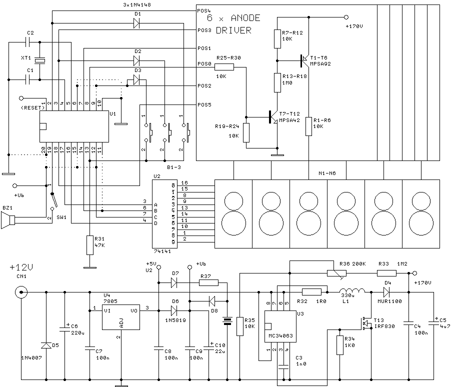
A key component of this design is the TTL IC 74141, which serves as a BCD (Binary Coded Decimal) decoder and high-voltage driver for controlling the individual digits of the nixie tubes. Given the scarcity of the 74141, alternative sourcing may be necessary, as it was a popular choice during the TTL logic era. The clock's design includes a TTL to high-voltage converter, which is essential for interfacing the low-voltage microcontroller signals with the high-voltage requirements of the nixie tubes.
For the high-voltage supply, the MC34063 step-up (boost) converter IC has been selected for its cost-effectiveness and availability. The converter circuit is adapted from the manufacturer’s datasheet, with modifications to enhance the power switch capability using an external transistor (T13) to handle the high voltage, as the internal switch of the MC34063 is not rated for such levels.
The printed circuit board (PCB) design is intended to accommodate a variety of microcontroller types, featuring a 20-pin socket that allows for easy adaptation. This universality in design facilitates the use of different microcontrollers by simply changing a few wire jumpers, thus providing flexibility for hobbyists and electronics enthusiasts.
In summary, this clock circuit is designed with safety and adaptability in mind, utilizing widely available components to create a functional and customizable nixie tube clock suitable for educational and hobbyist applications.The clock will have 6 digits and time setting will be done by means of a few buttons. I will try to use the most common types from widely used microcontroller families of miscellaneous producers. I will write the program in C language. Nixies need high voltage for operation. I wanted to avoid dangerous mains line voltage. The supply voltage for the clock must be safe 12 V. As the main target of the construction was toy, this instruction is not subtle construction with mechanical details and specified case.
You can modify the clock to your taste and qualification. Most of blocks in the block diagram are clear. Somewhat special is converter TTL/high voltage for nixies. Anode drivers are based on high voltage NPN and PNP transistors. I took the driver here. TTL IC 74141 ensures BCD decoder and high voltage driver for individual digits. Perhaps it will be difficult to come by 1 piece of it (I don't know if 74141 is produced still). But if you discovered nixies, 74141 could be near :-). In time of TTL logic fame the 74141 was almost exclusive alternative. So try to find one. Nixie need voltage about 170 V. It would be useless to design special circuit for voltage converter. There is a lot of IC for step-up (boost) converters. I selected low cost and widely available MC34063. The converter circuit is almost copied from data sheet. Just only power switch is strengthened by T13. Internal switch is not suitable for such high voltage. All microcontroller manufacturers design specific families and types. Pin configurations of individual types are various. I tried to design universal PCB for several microcontrollers. There is 20 pin socket on the board. You can adapt it for miscellaneous microcontrollers with a change a few wire jumpers. Types tested by me are listed below. You can try additional types. Processor option is advantageous. Amateur of electronics applies one microcontroller family usually and his hobby corner is equipped with programmer and tools for this family. It can be problem to use microcontrollers from other manufacturers. You can choose your favourite processor below. Ready for use is type, source and binary code, development tools and programmer. 🔗 External reference
Related Circuits
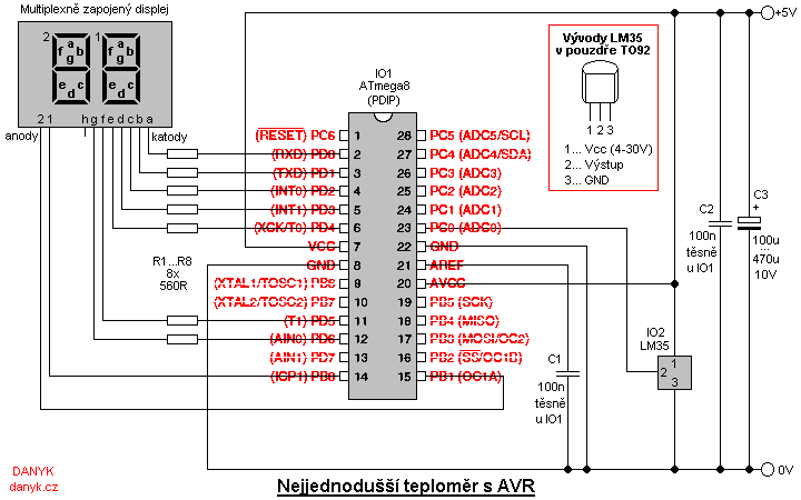
This is a simple digital thermometer utilizing an Atmel AVR microprocessor, capable of measuring temperatures in the range of 2 to 99 °C with a resolution of 1 °C. The circuit is managed by an Atmel AVR ATmega8, ATmega8L,...
Temperature sensor converter designed for use with a digital multimeter, capable of measuring temperatures from -40 °C to 110 °C. It features a state indicator and requires no calibration, utilizing the LM35 integrated circuit. The freezing point of water...
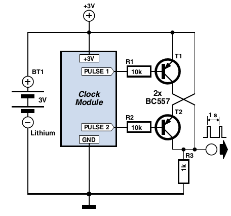
Many electronic projects require a timebase generator that is accurate to within a second. One method of achieving this is through the use of a microcontroller, quartz crystal, and appropriate software. However, a more cost-effective and straightforward approach is...
A digital storage oscilloscope (DSO) is a very important piece of test equipment that can do the jobs that a normal CRO just can't handle. Such as capturing single shot and widely spaced waveshapes, and looking at non-repetitive signals...
This electronic clock comprises the LM8365 and the LDD640R displays. The LM8365 can show the hour/minute and month/day. Users can set two alarm outputs, AD1 and AD2, by pressing either the 12h or 24h button. The operating voltage range...
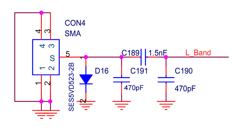
The implementation occurred in the higher frequency L-band (1452-1492 MHz), while the EU, AU, and GB operate in the VHF Band III (174-230 MHz). Unfortunately, it did not succeed for various reasons. The application works well locally, but only...
Warning: include(partials/cookie-banner.php): Failed to open stream: Permission denied in /var/www/html/nextgr/view-circuit.php on line 713
Warning: include(): Failed opening 'partials/cookie-banner.php' for inclusion (include_path='.:/usr/share/php') in /var/www/html/nextgr/view-circuit.php on line 713