
Digital code lock

The code lock circuit operates by utilizing two CD4013 dual flip-flop ICs, which are configured to manage the input and output states of the system effectively. The push button switches serve as the primary user interface, allowing the entry of a predetermined code. The connection of one terminal of each switch to +12V DC ensures that pressing any switch sends a high signal to the respective clock input of the flip-flops.
In the operational flow, when the first button corresponding to the code (in this case, '2') is pressed, it triggers the first flip-flop (IC1a). The grounded data input at pin 9 ensures that the output at pin 13 transitions to low (0), which is essential for the sequential logic required for the code entry. Each subsequent button press must follow the correct sequence to maintain the integrity of the code entry process. If the sequence is followed correctly, the final output from the last flip-flop (IC2b) will activate a transistor that drives the relay, allowing for the intended action, such as unlocking a door or enabling a device.
The reset mechanism is crucial for maintaining the lock's security. The combination of resistor R11 and capacitor C2 forms a timing circuit that controls how long the lock remains in the unlocked state after the correct code has been entered. The capacitor charges when the transistor is activated, and once it reaches a certain voltage threshold, it triggers a reset condition for the flip-flops, thereby restoring the system to its initial locked state. This feature ensures that the lock cannot remain in an unlocked state indefinitely, adding an extra layer of security.
The values of R11 and C2 can be adjusted to modify the timing of the automatic reset, allowing for customization based on the specific application requirements. This flexibility makes the code lock circuit suitable for various uses where temporary access is needed without compromising security.This is a simple but effective code lock circuit that has an automatic reset facility. The circuit is made around the dual flip-flop IC CD4013. Two CD 4013 ICs are used here. Push button switches are used for entering the code number. One side of all the push button switches are connected to +12V DC. The remaining end of push buttons 2, 3, 6, 8 is con nected to clock input pins of the filp-flops. The remaining end of other push button switches are shorted and connected to the set pin of the filp-flops. The relay coil will be activated only if the code is entered in correct sequence and if there is any variation, the lock will be resetted.
Here is correct code is 2368. When you press 2 the first flip flop(IC1a) will be triggered and the value at the data in (pin9) will be transferred to the Q output (pin13). Since pin 9 is grounded the value is 0 and so the pin 13 becomes low. For the subsequent pressing of the remaining code digits in the correct sequence the 0 will reach the Q output (pin1) of the last flip flop (IC2b).
This makes the transistor ON and the relay is energised. The automatic reset facility is achieved by the resistor R11 and capacitor C2. The positive end of capacitor C2 is connected to the set pin of the filp-flops. When the transistor is switched ON, the capacitor C2 begins to charge and when the voltage across it becomes sufficient the flip-flops are resetted. This makes the lock open for a fixed amount of time and then it locks automatically. The time delay can be adjusted by varying the values of R11 and C2. 🔗 External reference
Related Circuits

Another application of the frequency-to-voltage converter (FVC) is the tone/frequency decoder. This circuit is designed to identify the frequency band of an oscillating signal. It is utilized in various applications, such as determining the frequency band in signals and...
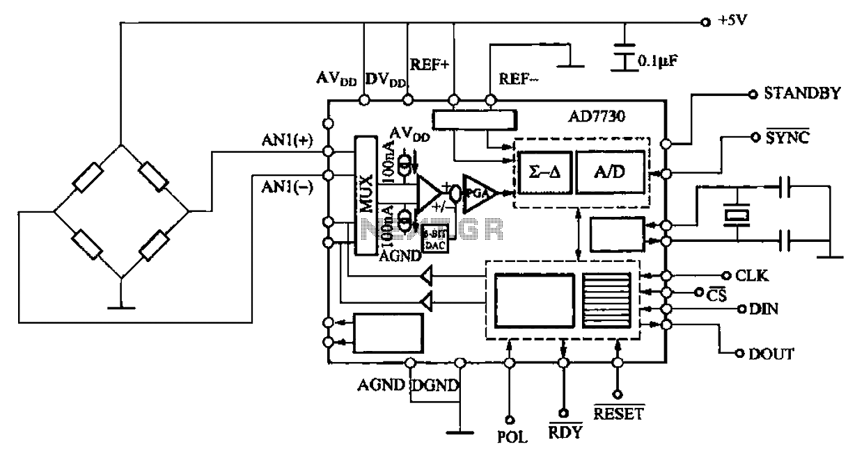
AD7710/7715/7730 multifunction digital sensor signal conditioning integrated circuits (ICs) that combine a digital interface with a control port, a clock generator, a digital filter, amplitude modulation, a programmable gain amplifier, an analog-to-digital (A/D) converter, and additional electrical pathways. The...
This digital DIY tachometer for bicycles utilizes two reed switches to gather speed information. The reed switches are positioned near the wheel rim, where permanent magnets, attached to the wheel spokes, pass by and activate the switches. The speed...
The aim of this project was to get a digital camera into a small electric radio controlled (RC) aeroplane and still have it fly. The aeroplane shown, a park flyer, weighs between 400 and 550 grams depending on the...
This clock timer utilizes a PIC16F628 microcontroller to display a 3.5-digit time format and control an external load. It is programmable to time intervals from 1 to 59 minutes. The clock features a calendar that accounts for leap years...
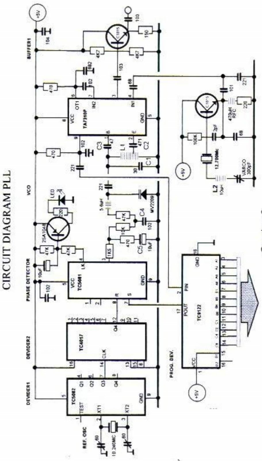
The primary function of the phase-locked loop (PLL) phase detector is to compare the input phase of the voltage-controlled oscillator (VCO) signal with a reference signal, resulting in a phase difference. This phase difference generates a voltage difference, which...