
PIC16F628 Digital Clock Timer circuit and explanation
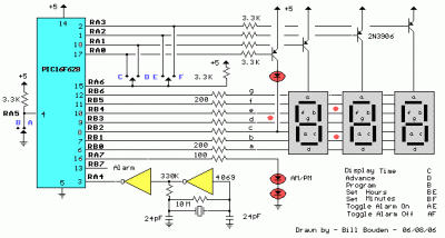
The clock timer circuit employs the PIC16F628 microcontroller, chosen for its efficiency and capability to manage both timing and display functions. The microcontroller interfaces with a 3.5-digit seven-segment display to present the time in a clear, readable format. The display is driven by a suitable driver circuit that ensures proper voltage levels and current to illuminate the segments effectively.
For timing functionality, the microcontroller utilizes an internal timer that can be programmed for specific intervals, allowing for precise control over the timing operation. The user can input desired time settings through a keypad or switches connected to the microcontroller, facilitating easy adjustments.
The calendar function is implemented through the microcontroller's programming, which includes leap year calculations and the ability to adjust for daylight savings time. This ensures that the clock remains accurate throughout the year, requiring minimal user intervention.
The correction feature is particularly useful in maintaining timing accuracy over extended periods. By allowing the addition of an extra second at specified intervals, the design compensates for any drift that may occur due to the inherent characteristics of the oscillator. The selection of a 32.768 kHz crystal is standard in timing applications due to its stability and low power consumption, making it ideal for battery-operated devices.
To enhance the oscillator's performance, a 24pF capacitor is included in the circuit, which can be adjusted to fine-tune the frequency output. This adjustment capability is crucial for ensuring that the clock timer maintains accurate timekeeping, especially in environments where temperature fluctuations may affect the oscillator's performance.
Overall, this clock timer circuit design offers a robust solution for timekeeping and load control applications, integrating programmable features and correction mechanisms to ensure reliable operation.This clock timer uses a PIC16F628 microcontroller to display 3 and 1/2 digit time and control an external load. It can be programmed to time from 1 to 59 minutes. The clock includes a calendar with leap year and optional daylight savings adjustments. The timer output can be set from 1 to 59 minutes and manually switched on and off. The clock also has a correction feature that allows an additional second to be added every so many hours to compensate for a slightly slow running oscillator. The oscillator uses a common 32. 768 KHz watch crystal and the frequency can be adjusted slightly with the 24pF capacitor on the right side of the crystal.
Disclaimer All files are found using legitimate search engine techniques. This site does not and will not condone hacking into sites to create the links it list. We will and do assume that all links found on the search engines we use are obtained in a legal manner and the webmasters are aware of the links listed on the search engines. If you find a URL that belongs to you, and you did not realize that it was "open to the public", please use the report button to notify the blogmaster of your request to remove it or it will remove within 24 hours.
This is not an invitation for webblog haters to spam with requests to remove content they feel that is objectionable and or unacceptable. Proof of URL ownership is required. NOTICE: This Blog Has Already Been Reviewed And Accepted By Blogger. com 🔗 External reference
Related Circuits
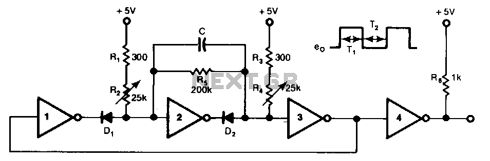
This free-running TTL square-wave oscillator features a variable frequency output spanning a 20:1 range or better. It utilizes four of the six inverters in an SN7404 chip along with additional components. The frequency of oscillation is dictated by the...
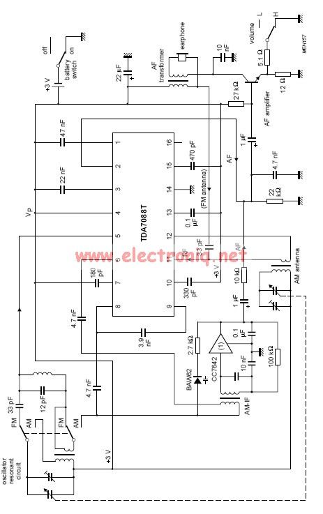
The TDA7088 features a frequency-locked-loop (FLL) system with an Intermediate Frequency (IF) of approximately 70 kHz. This circuit can be powered using a 3-volt battery cell or a regulated power supply. The TDA7088 is a highly integrated FM radio receiver...

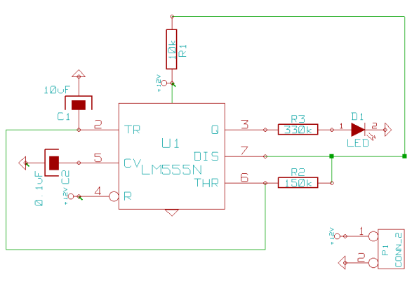
This circuit is designed as a countdown timer utilizing a countdown calculation. It employs the 555 integrated circuit (IC) as the primary control element. The 555 IC functions as a counter and a transistor switch to activate a relay...
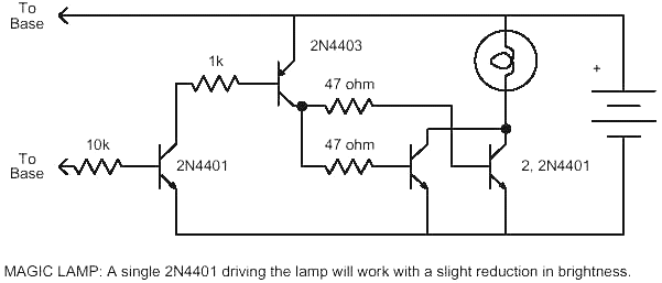
This magic lamp appears to be an ordinary frosted light bulb with a rather unusual characteristic. Whenever a finger touches the base threads and center contact, the lamp magically lights up without wires. It creates a compelling illusion if...
This page outlines how to create a simple theft deterrent that can be quite effective. The concept involves using a flashing red LED to indicate that the vehicle is protected. This device serves to safeguard the car from potential...
This is a VU meter analog circuit. The circuit is connected to the line terminals of the amplifier. The VU meter operates simply, with T1 and T2 indicating signal increases. The VU meter circuit is designed to visually represent audio...