
Digital HF Antenna Analyser
The microprocessor-based antenna analyzer operates within a frequency range of 1.6 to 33 MHz, making it suitable for various amateur radio applications. The core of the device is the 87C552 microcontroller, which interfaces with a two-line LCD display. The display shows essential parameters such as frequency, resistive and reactive impedance components, and VSWR, facilitating real-time monitoring and analysis for users.
The measurement process begins with the signal input from the antenna, which is fed into a bridge circuit designed to minimize complex calculations. The bridge circuit is essential for determining the impedance characteristics of the connected antenna. The output from the bridge is processed by the microcontroller, which calculates the real and reactive components of the impedance and the VSWR based on the reference impedance of 50 ohms.
The design emphasizes ease of use and accuracy. The microcontroller performs necessary calculations efficiently, allowing for quick updates on the LCD display. The prototype’s performance, achieving a measurement accuracy within 5%, aligns with the expectations for amateur-grade equipment, making it a reliable tool for radio enthusiasts.
In summary, this microprocessor-based antenna analyzer represents a significant advancement over traditional analog designs, offering enhanced functionality, ease of use, and accurate measurements of complex impedance, which are crucial for optimizing antenna performance in amateur radio applications.This instrument measures complex impedance over the 1. 6 - 33 MHz HF spectrum. It also calculates and displays the VSWR of the impedance referenced to 50 ohms. The most common application of the meter is as an antenna analyser. The design was published in `Break-In`, New Zealand`s amateur radio magazine in Jan/Feb 2006, and is republished here with the permission of the editor. Note: `Break-In` is a term used in amateur radio to describe a system which allows another person`s signal to be heard in the brief intervals between transmitted Morse Code symbols. Why is it that having reached the top of the mountain and just begun to enjoy the rewards of the climb, you realise that there`s another peak just that little bit higher to be seen in the distance Such was the case a month or so after I completed an analog antenna analyser.
The analog meter did everything demanded of it, but there were times when a little more information would have been useful. I`d seen the next mountain top. (The analog meter is described on another page on this website) I discovered, for example, that there are times when full information about the complex impedance being measured can be useful.
An impedance is made up of two components; the real or resistive part, R`, and the reactive part, X`. The reactive component may be capacitive or inductive. Complex impedance can be displayed in two ways; Either as a magnitude plus a phase angle (i. e. A magnitude of "A" ohms at a phase angle of "B" degrees) or as a series combination of real and reactive components (i.
e. C +/- jD ohms) where j` indicates the value of "D" is reactive. If "D" is positive, the impedance is inductive. If negative, the impedance is capacitive. While it is possible to measure and display these components of a complex impedance using analog circuitry, this type of equipment can be complex. It is possible however to build some simple circuitry, and by making a careful series of analog measurements, some calculations will allow the real and reactive components of a complex impedance to be determined.
An example is the "three meter" method used by Peter Dodd, G3LDO (See references 1 and 2, for example) (Note: All references appear at the end of this webpage). Another popular approach uses the bridge described in my page on the analog antenna analyser. These days, it`s far easier to use a microprocessor to carry out both measurements and calculations. Well, OK, it`s easy to say, but more difficult and time-consuming to do! (The calculations required are briefly summarised in Appendix A for those interested in the details) This page, then, describes this microprocessor-based antenna analyzer.
It uses the 87C552, a device from the 8051 family, and it uses a standard two line LCD display to show frequency, resistive and reactive impedance components, and VSWR, over the range 1. 6 to 33 MHz. The prototype was able to measure impedance typically within 5%, in line with results reported for most amateur-grade commercial analysers.
Here`s the basic block diagram of an antenna analyser (See below - Right click for a closer look) Those interested in further general information on antenna analysers should also see my other page describing the analog version of this instrument. The bridge and detector section is the key part of these meters. There are a number of bridge designs available. One of the most commonly used methods is the four element bridge. This is the type used in my other earlier analog analyser. In this case, however, I required a bridge which minimised the number of complex calculations to be performed by the microprocessor.
That ruled out the four element type. It also ruled out the three-meter bridge. This requires some coplicated sine and cosine calculations, or the use of some large lookup tables. In a touch of serendipity, I happened across some work by Jim Tregellas, VK5JST at a timely moment. This was subsequently 🔗 External reference
Related Circuits
S/PDIF is an acronym for Sony /Philips Digital Interface (or Sony /Philips Digital Interconnect Format). The full specification for the S/PDIF interface consists of hardware and software, but only the hardware side will be discussed here - the software...
This circuit measures the distance covered during a walk. The hardware is housed in a small box that can be slipped into a pocket, and the display is designed as follows: the leftmost display D2 (the most significant digit)...
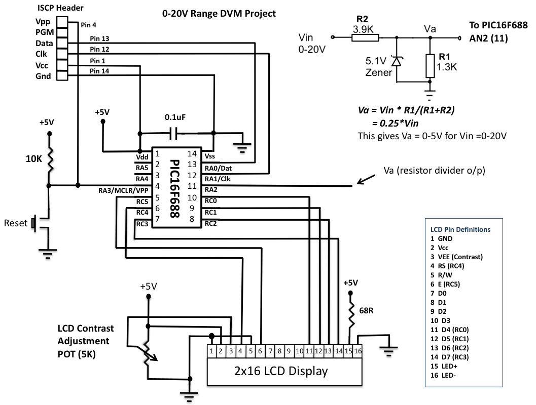
This is another version of an older digital voltmeter (DVM) project that was based on the PIC12F683 microcontroller. The previous version displayed the measured voltage on an LCD driven serially by the PIC12F683 using three I/O pins. The new...
The reason why I am using an LCD display is because it allows me to display many characters and it doesn't need to be refreshed as 7-segment LED displays. Also, the interface requires less I/O pins. For this project,...

A digital tachometer and speedometer utilizing a seven-segment display was initially attempted but not successfully implemented due to overcrowding of integrated circuits (ICs) and components. An LED tachometer was successfully constructed later, followed by the development of an LED...
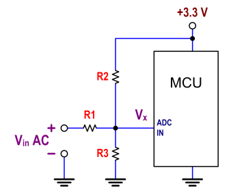
The ATtiny24 microcontroller's ADC is utilized to record an AC signal, which operates within a voltage range of 0 to 3.3V. A precision rectifier is employed to eliminate the negative portion of the signal. The circuit incorporates an LMC6484...