
microcontroller Analog to Digital Converter and Negative Voltages
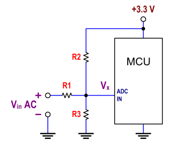
The circuit in question employs an ATtiny24 microcontroller with an integrated analog-to-digital converter (ADC) to measure an AC signal. The ADC's operational range is limited to 0-3.3V, necessitating the use of a precision rectifier to convert the AC signal into a suitable DC level for accurate measurement. The precision rectifier, based on the LMC6484 operational amplifier, is configured with the V+ rail connected to a 3.3V supply and the V- rail grounded. This configuration allows the op-amp to amplify the positive half-cycles of the AC signal while effectively eliminating the negative half-cycles.
The choice of 1N4004 diodes is appropriate for this application, as they provide reliable rectification with low forward voltage drop. The resistors used in the circuit, rated at 10kΩ, help set the gain of the op-amp and stabilize the output. Despite the intended design, the output observed on the oscilloscope indicates a voltage swing from -0.5V to 1V, which suggests that the precision rectifier is not entirely eliminating the negative voltages as expected. This discrepancy could be due to several factors, including the op-amp's output limitations or the diode's forward voltage characteristics.
The microcontroller's ADC displays a range of 0V to 1.5V, which indicates that the rectified signal is being processed correctly in terms of waveform shape; however, the voltage range does not align with the expected output. When a simple diode-resistor combination is tested, the output range shifts to -0.X to Y volts, demonstrating that the rectification method significantly impacts the resulting voltage levels.
The presence of a minor negative voltage in the output, even with the precision rectifier, suggests that there may be an offset in the circuit that needs to be addressed. The logger's ability to graph the results indicates that while the signal is being captured, the negative values are being shifted to zero, effectively expanding the range of the output compared to the input. The logger's performance with positive voltages confirms its accuracy in reading and tracking waveforms, indicating that the primary issue lies in the rectification process and the resulting voltage range.
To resolve these issues, a thorough review of the precision rectifier circuit is recommended, including checking for proper component values, ensuring the op-amp is functioning within its specifications, and verifying that the diodes are correctly oriented and operational. Adjustments to the circuit design may be necessary to achieve the desired performance and eliminate any unwanted negative voltages in the output.Using the ADC on an ATtiny24 to record a AC signal. The ADC has a range from 0-3. 3V. I`m using a precision rectifier to get rid of the negative portion of the signal. I`ve attached a picture of the circuit I`m using for the rectifier. I`m using an LMC6484 as the op-amp with 3. 3V to the V+ rail and 0 to the V- rail. I`m using 1N4004`s as the di odes and 10k for the resistors. My logger is able to graph the waveform of the rectifier very well. BUT the oscope shows that the output of the rectifier varies from -0. 5 to 1V. But my micro shows a signal with the same waveform that goes from 0-1. 5V! If I replace the precision rectifier with a simple diode/resistor combination, I get a waveform that varies from -0. X volts to Y volts (depending on the input through the function generator). The micro follows the shape of the waveform correctly but the voltage range is from 0. X to Y volts. I always have a little bit of a negative signal even with the precision rectifier and when I graph the results through my logger, it appears that the largest negative value has been moved up to zero, so I seem to get a larger range than the input.
I`ve input positive voltages into the logger through a power supply, and it reads those voltages perfectly! It follows the shape of the waveforms very well too. The only problem seems to be the range. I`m completely lost. 🔗 External reference
Related Circuits
The digital readout of the Corsair 560 is positioned above the tuning knob. In this radio, the six-digit display often fluctuated, frequently doubling the frequency indication. The reading was unstable, making it challenging to determine the tuned frequency. After...
This is the second instructable focused on creating a digital watch as a learning experience. An Atmega644 chip from a Sanguino was available, which would have sufficed, but the intention was to burn an Arduino bootloader and test its...
Communication with the MCP3028 ADC chip is achieved through a straightforward serial interface that adheres to the SPI protocol. The PIC16F84 or PIC16F628 does not possess a hardware SPI peripheral. However, a software-implemented SPI protocol can facilitate communication with...
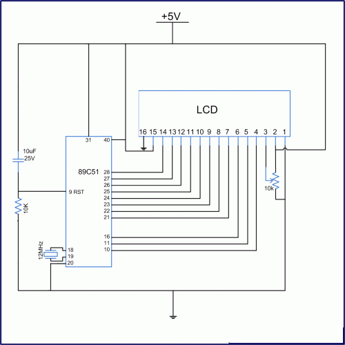
Interface the LCD with the 8051 microcontroller AT89S52. However, upon powering up the microcontroller, the LCD displays only black boxes. Multiple codes have been tried, but the output remains the same. The circuit has been simulated in Proteus, where...
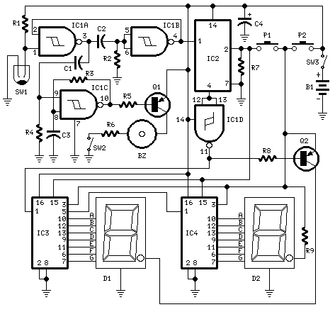
This circuit measures the distance covered during a walk. Hardware is located in a small box slipped in pants pocket and the display is conceived in the following manner: the leftmost display D2 (the most significant digit) shows 0...
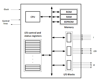
Microcontrollers are integrated circuits that consist of a microprocessor along with additional units such as memory and input/output peripherals. This implementation allows for savings in time, space, and cost. Microcontrollers are commonly abbreviated as MCU (Microcontroller Unit), µC, or...