
Digital oscillator
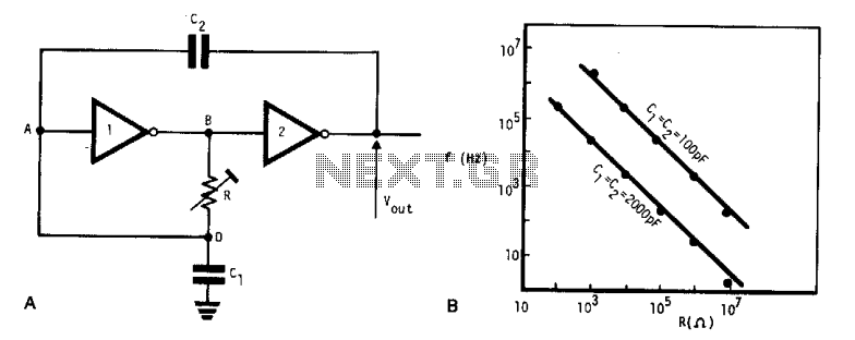
The described oscillator circuit utilizes two CMOS buffer inverters which serve as the primary active components for generating oscillations. The configuration of these inverters allows for feedback that sustains oscillation. The two capacitors (C1 and C2) are crucial for determining the timing characteristics of the oscillator. When both capacitors are equal in value, the frequency of oscillation can be calculated using the formula:
\[ f = \frac{1}{2 \pi R C} \]
where \( R \) is the resistance set by the variable resistor and \( C \) is the capacitance value of either capacitor (since C1 = C2).
The variable resistor allows for fine-tuning of the oscillation frequency, providing flexibility in applications where different frequencies may be required. The operating voltage range of 4 V to 18 V indicates that this oscillator can be used in various low-power applications, making it suitable for battery-operated devices or low-voltage circuits.
In terms of input and output impedance, the circuit's performance may be influenced by these parameters. However, they are typically considered negligible for the basic operation of this oscillator. When implementing this circuit, it is essential to ensure that the power supply is stable and within the specified voltage range to maintain consistent oscillation performance.
Overall, this CMOS-based oscillator circuit is an efficient solution for generating square wave signals in various electronic applications, including timers, clock generators, and signal modulation systems. Its simplicity and low cost make it an attractive option for hobbyists and professionals alike.This very simple, low cost oscillator, is built with two CMOS buffer inverters, two capacitors and a variable resistance. The circuit can work with voltages ranging from 4 V up to 18 V. If Cl = C2, the frequency of oscillation. Ignoring the output and input impedance is given. 🔗 External reference
Related Circuits
The circuit was designed to create an electronic oscillator known as a Wien Bridge Oscillator, which can be used for the creation of low-frequency sine waves. The Wien Bridge Oscillator is a type of electronic oscillator that generates sine waves....
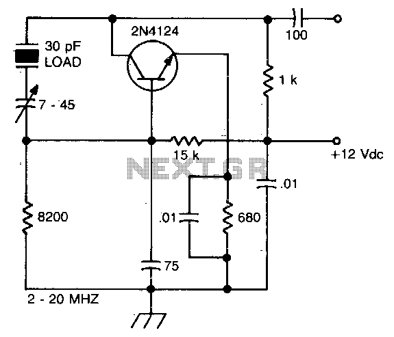
The crystal is part of a feedback circuit connecting the collector to the base. A trimmer capacitor in series adjusts the point on the reactance curve where the crystal operates, allowing for frequency trimming. The capacitor exhibits negative reactance,...
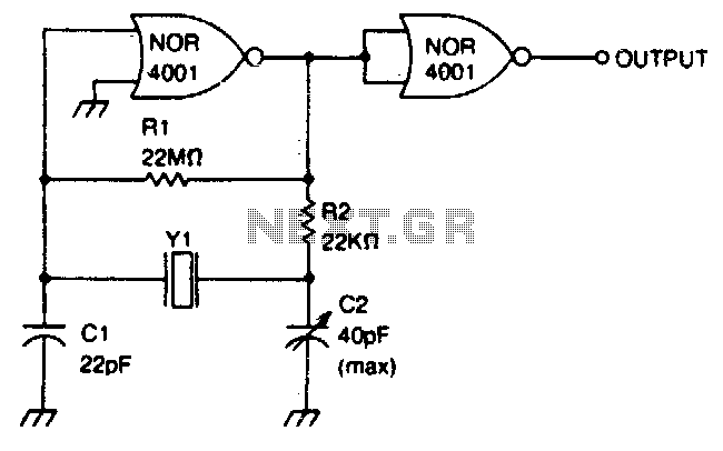
This circuit operates within a frequency range of 0 MHz to 2 MHz. The frequency can be finely adjusted to a specific value using the trimmer capacitor C2. Additionally, the second NOR gate functions as an output buffer. The circuit...
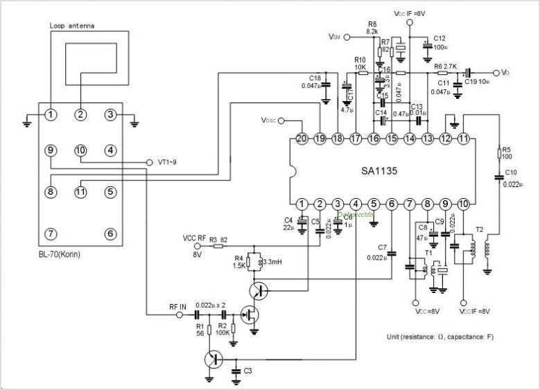
The SA1140 is an intermediate frequency (IF) system integrated circuit (IC) tailored for FM car stereo receivers. It offers adaptable muting characteristics that can be modified using external components. Manufactured by Silan. The SA1140 is engineered to enhance the functionality...
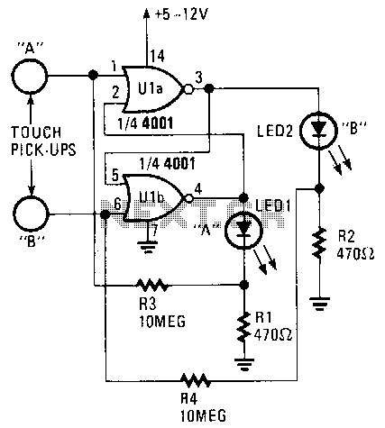
Only one LED can be illuminated when the circuit is at rest. The illuminated LED is determined by the touch pick-up that last had human contact. Pickup terminal A controls the on condition of LED1, while terminal B controls...
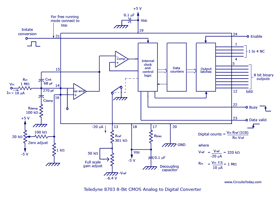
The basic analog to digital (A/D) converter circuit has been previously explained. In addition to this, various types of monolithic analog to digital converters exist, including the integrating A/D, integrating A/D with three-stage outputs, and the tracking A/D with...