
Cmos crystal oscillator
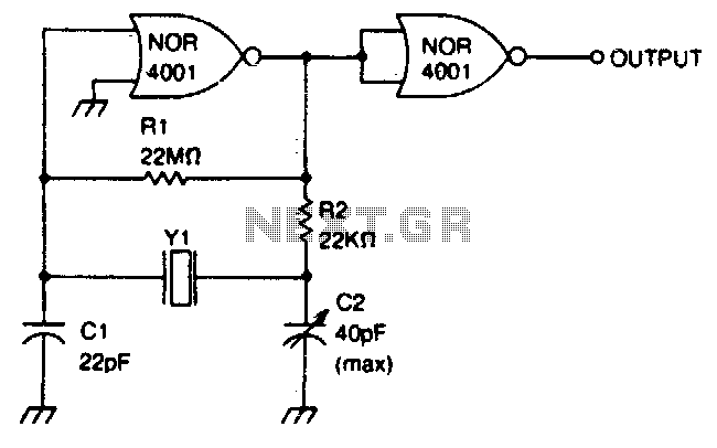
The circuit design includes a frequency generator capable of producing signals within the specified range of 0 MHz to 2 MHz. The primary component responsible for frequency adjustment is the trimmer capacitor C2, which allows for precise tuning of the output frequency. This feature is crucial for applications requiring specific frequency outputs, such as in communication systems or signal processing.
The inclusion of a second NOR gate as an output buffer enhances the circuit's performance by isolating the frequency generation stage from the load. This buffering action prevents loading effects that could alter the frequency or amplitude of the output signal. The NOR gate configuration also provides a robust output stage, ensuring that the circuit can drive subsequent stages effectively without distortion.
In practical applications, this circuit can be utilized in various electronic devices where adjustable frequency signals are necessary. The design's simplicity and effectiveness make it suitable for educational purposes as well as in professional environments where precise frequency control is required. The careful selection of components, including the trimmer capacitor and NOR gates, contributes to the overall reliability and functionality of the circuit.This circuit has a frequency range of 0 MHz to 2 MHz. Frequency can be adjusted to a precise value with trimmer capacitor C2 The second NOR gate serves as an output buffer. 🔗 External reference
Related Circuits
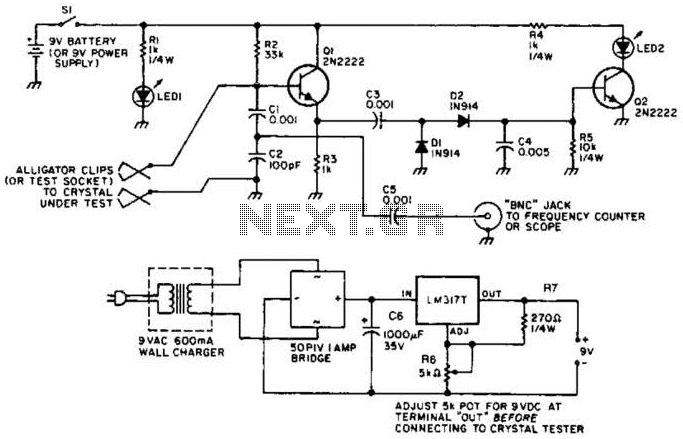
Q1 functions as a Colpitts crystal oscillator. If the crystal being tested is operational, the RF signal is rectified by diodes D1 and D2, which activates Q2 and illuminates indicator LED2. Additionally, LED1 serves as a power indicator. The circuit...
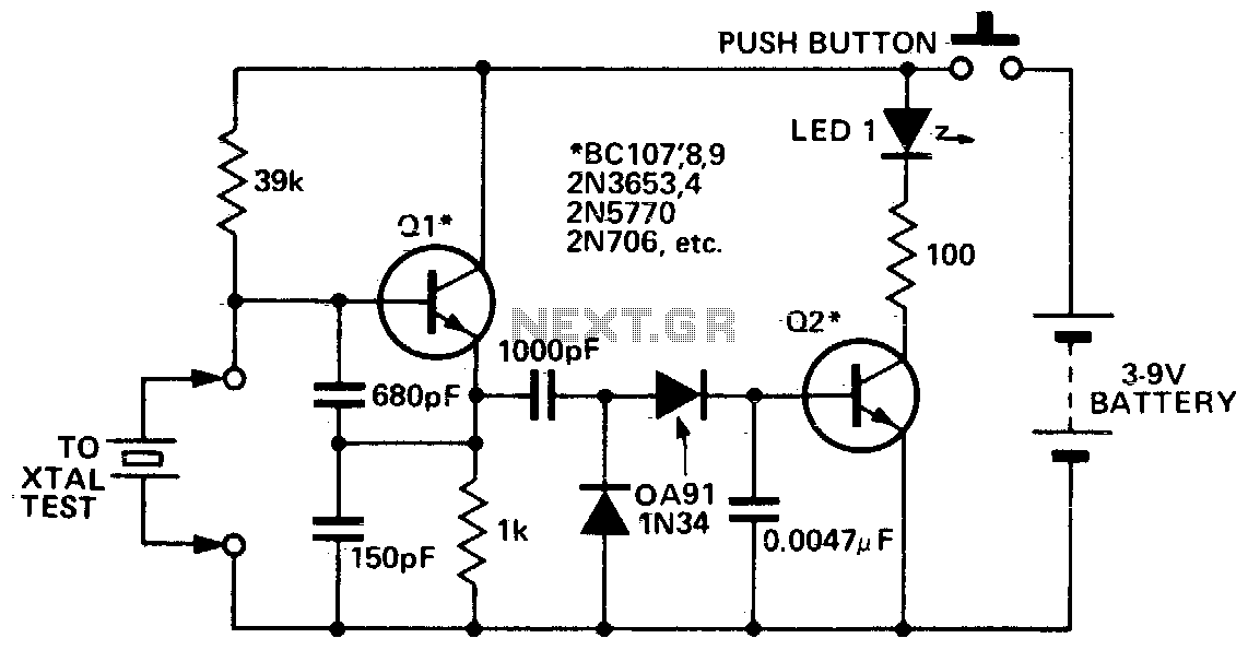
This circuit is designed to check fundamental oscillations. When Q2 conducts, the LED lights up. It operates with A3 HF crystals on a "Go-No-Go" basis. An untuned or 6V, 40mA bulb can be used in place of the Colpitts...
A basic Wien Bridge Oscillator utilizes a filament lamp in conjunction with an operational amplifier (op-amp). The property of filament lamps, specifically the non-linear increase in resistance of the tungsten filament as it heats, plays a crucial role in...
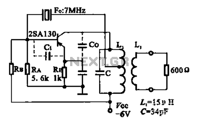
The 2SA130 transistor is used in an oscillator circuit with an oscillation frequency of 7 MHz. The power supply voltage is 6V, and the load is a frequency-selective resonant circuit with a quality factor of 600. The circuit utilizes the...
A CD4017 is configured as a senary counter, with an input clock frequency of 300 Hz. Diodes VD1 to VD9 and resistors R1 to R3 form three three-input OR gates, which can each receive two 50 Hz three-phase wave...
The 32-kHz low-power clock oscillator provides several advantages compared to traditional oscillator circuits that utilize a CMOS inverter. These inverter circuits often exhibit issues such as significant fluctuations in supply currents across a 3V to 6V supply range, making...
Warning: include(partials/cookie-banner.php): Failed to open stream: Permission denied in /var/www/html/nextgr/view-circuit.php on line 713
Warning: include(): Failed opening 'partials/cookie-banner.php' for inclusion (include_path='.:/usr/share/php') in /var/www/html/nextgr/view-circuit.php on line 713