
Digital Step-Km Counter
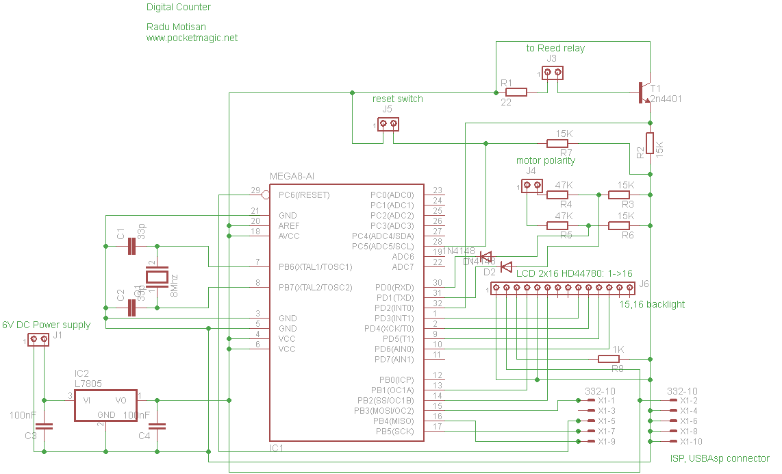
The digital step-kilometer counter is designed to accurately measure and display the distance traveled in meters. The core of the circuit typically consists of a microcontroller or a digital counter IC, which processes input from a step detection mechanism, such as a piezoelectric sensor or a simple mechanical switch activated by footfalls.
The resistors R1 and R3, both rated at 22K ohms, are used for biasing and setting thresholds within the circuit. They may be part of a voltage divider network that helps in conditioning the signal from the step detection mechanism before it is fed into the microcontroller. The power supply for the circuit can be sourced from a small battery, ensuring portability and ease of use.
The output display is likely a two-digit seven-segment LED or LCD display, which shows the distance in meters. The microcontroller processes the input signal and increments the displayed value based on the number of steps detected, converting this into a distance calculation based on a predetermined step length.
To enhance usability, the device may include additional features such as a reset button to clear the distance counter, and possibly a mode switch to toggle between different measurement units or settings. The compact design allows for easy carrying in a pocket, making it an ideal companion for fitness enthusiasts engaged in walking or jogging activities.
Overall, this digital step-kilometer counter combines simplicity with functionality, providing users with a reliable method to track their distance traveled during physical activities.Digital Step-Km Counter. Max. range: 9,950 meters with two digits. Slip it in pants` pocket for walking and jogging. Circuit diagram: Parts: R1,R3 22K 1/4W. 🔗 External reference
Related Circuits
When it is necessary to transmit a digital signal between two electrically isolated circuits, an optoisolator or transformer coupling is typically employed. However, both solutions have limitations; optocouplers are effective only up to approximately 10 MHz, while transformers exhibit...

This circuit is used for a Digital Radar Speedometer. It allows for the measurement of the speed of any moving object, particularly vehicles such as cars. The speed is displayed in kilometers per hour (KPH) with a three-digit display....
This very simple counter can be used to measure the frequency of various wireless devices. Applies in reviving the transmitter and its operation as a control monitor frequency. It can be used as a scale to the receiver. Due...
The circuit utilizes an Atmega8-8PU microcontroller configured for 8MHz operation with an external crystal oscillator. It incorporates a Nokia 5110 LCD and a transistor to manage the pulses generated by a reed relay. A 3.3V voltage regulator supplies power...
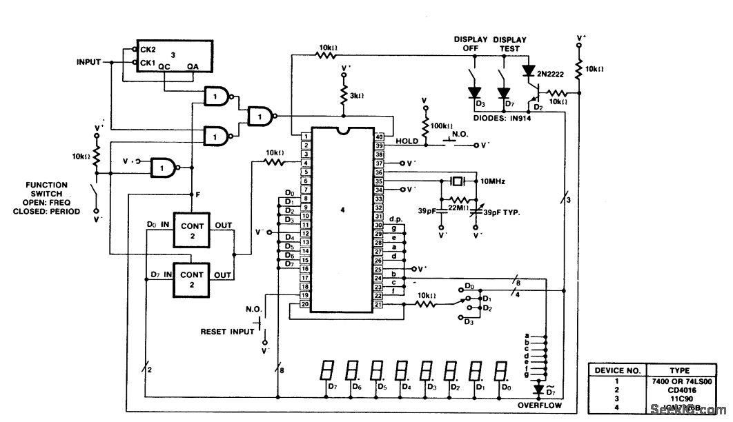
A 100 MHz frequency and period counter is constructed using the Intersil ICM7226B in a 40-pin DIP package. This circuit incorporates a CD4016 analog multiplexer to route the digital outputs back to the function input. The CD4016 operates as...
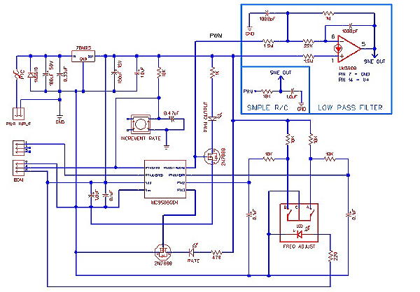
In an analog world, converting digital values to their analog equivalents is often necessary when using microcontrollers. Many low-cost microcontrollers lack built-in hardware digital-to-analog converters (DACs), but most feature an 8-bit or 16-bit timer capable of generating Pulse Width...
Warning: include(partials/cookie-banner.php): Failed to open stream: Permission denied in /var/www/html/nextgr/view-circuit.php on line 713
Warning: include(): Failed opening 'partials/cookie-banner.php' for inclusion (include_path='.:/usr/share/php') in /var/www/html/nextgr/view-circuit.php on line 713