
Coil Winding machine counter with Atmega8 and Reed relay
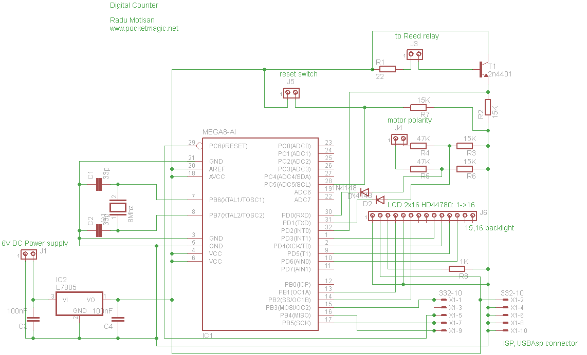
The circuit design features a microcontroller at its core, the Atmega8-8PU, which operates at an 8MHz frequency facilitated by an external crystal oscillator. This microcontroller interfaces with a Nokia 5110 LCD, providing a user interface for displaying relevant information, such as the counter value and motor status. The transistor, connected to the reed relay, functions as a switch that allows the microcontroller to read the state of the relay, which is crucial for the operation of the system.
Power management is handled by a 3.3V voltage regulator, which ensures that all components receive stable and appropriate voltage levels. The regulator is fed by a 5V power supply, which is a common voltage level for many electronic components. The test board is designed for easy connection and troubleshooting, featuring headers for programming and component connections, ensuring that the system can be easily modified or updated.
The polarity detection mechanism is critical for the functionality of the counter. The two-pin connector (J4) is strategically connected in parallel to the coil winding machine's motor, allowing the circuit to monitor the motor's polarity. The voltage dividers formed by resistors R3-R4 and R5-R6 play a vital role in adjusting the input voltage to a safe level for the microcontroller, preventing damage while ensuring accurate readings.
In normal operation, when the motor is connected with the correct polarity, the microcontroller detects a high signal on PD0, indicating that the counter should increment. Conversely, if the motor is reversed, resulting in a high signal on PD1, the counter will decrement. This feedback mechanism is essential for maintaining accurate counts in applications such as coil winding, where precise control over the number of turns is necessary.
Overall, this circuit design merges various components and functionalities to create a robust solution for monitoring and controlling a coil winding machine, ensuring both user interaction through the LCD and precise motor control through polarity detection.Using an Atmega8-8PU (configured for 8MHz with external crystal), a Nokia 5110 lcd, and a transistor to handle the pulses from a reed relay. A 3. 3V regulator provides the voltage for the entire circuit. Everything has been mounted on a test board, including the headers for: ISP programmer ( USBAsp ), the 5110 Nokia LCD, the power supply (5V in, fed to the 3.
3V regulator), the Reed relay connector, the reset button connector and another 2 pins connector, used to read the polarity of coil winding machine`s motor, so we know we either increment or decrement the counter. J4: is the polarity connector. It must be connected in parallel on the coil winding machine`s motor. It was designed for a 12V motor (but this can be changed by adjusting the voltage dividers formed by R3-R4 and R5-R6, so they take in the motor voltage, and output not more than 5V).
If the motor is connected in normal polarity, we will read PD0 high, if the motor is in inverse polarity, we`ll have PD1 high. This info is used in the code to either increment or decrement the counter. 🔗 External reference
Related Circuits
Some relays will become warm if they remain energized for some time. The circuit shown here will actuate the relay as before but then reduce the hold current through the relay coil by about 50%, thus considerably reducing the...
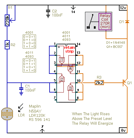
The first circuit energizes the relay when the light rises above the preset level. The second circuit energizes the relay when the light falls below the preset level. The two circuits are practically identical. The only difference between them...

Q1 is used as an oscillator operating at approximately 300 kHz. Resistor R9 is configured to allow the oscillator to initiate its operation. An object near the antenna will load the circuit, causing the oscillations to cease. This change...
This circuit is similar to the previous one but incorporates a photoresistor to trigger the flip-flop instead of a push button. A bias resistor is placed in series with the photoresistor to ensure that adequate voltage is present at...
This project shows you how to build a relay controller using the Basic Stamp I interfaced to the PC serial port. The Visual Basic 5 software developed for the interface lets you interact with the Basic Stamp to turn...
Humans have been using light and sound to achieve altered states of consciousness for thousands of years. Primitive cultures used flickering fires and rhythmic drumming to induce these altered states. Today, you can choose from a wide variety of...