
Digital switch for your camera
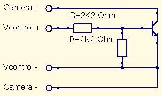
A digital switch for a camera can be implemented using a microcontroller, such as an Arduino or Raspberry Pi, along with a few additional electronic components. The primary function of this circuit is to control the camera's shutter release, allowing for automated photography.
The basic components required for this project include a microcontroller, a transistor or relay to act as a switch, a resistor, and connecting wires. The microcontroller will be programmed to send a signal to the transistor or relay, which will then close the circuit and trigger the camera's shutter.
The circuit can be laid out as follows:
1. **Microcontroller**: The microcontroller serves as the brain of the operation. It should be programmed to send a digital signal at specified intervals or in response to specific conditions, such as a sensor input.
2. **Transistor/Relay**: A transistor can be used to switch the camera's shutter. When the microcontroller outputs a HIGH signal, the transistor allows current to flow, simulating a button press on the camera. Alternatively, a relay can be used for higher current applications, providing electrical isolation between the microcontroller and the camera.
3. **Resistor**: A resistor is typically placed in series with the base of the transistor to limit the current flowing into it, ensuring that the transistor operates within safe limits.
4. **Power Supply**: Ensure that the circuit is powered appropriately. The microcontroller should be powered via USB or a suitable battery, while the camera may require its own power source depending on the design.
5. **Connections**: The shutter release cable of the camera should be connected to the collector of the transistor or the relay's normally open contact. The emitter of the transistor should be connected to ground, while the base is connected to a digital output pin of the microcontroller through the resistor.
By utilizing this setup, users can automate the photography process, allowing for time-lapse photography, remote shooting, and other creative applications. Proper programming and testing are essential to ensure reliable operation and to avoid any potential damage to the camera.This is a very easy instructable to build a digital switch for your camera in order to take photos with your microcontrollers. What you need: 1.. 🔗 External reference
Related Circuits
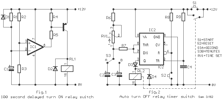
A 100 second delayed turn ON relay RL1 switch, if plug power +12V in circuit. In Fig.2 see a two range 6-60 second and 1-10 minute auto turn off relay timer circuit, with 555. Part List R1=1 Mohms C4=100nF...
This circuit is designed to digitally adjust the volume of an analog audio signal. It employs a single AVR microcontroller to generate a pulse width modulated (PWM) signal for control. The innovation of the circuit lies in the utilization...
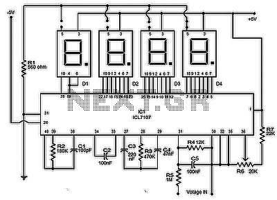
The circuit presented is a highly useful and accurate digital voltmeter featuring an LED display, utilizing the ICL7107 integrated circuit from Intersil. The ICL7107 is a high-performance, low-power, 3.5-digit analog-to-digital converter (ADC). This IC incorporates internal circuitry for seven-segment...
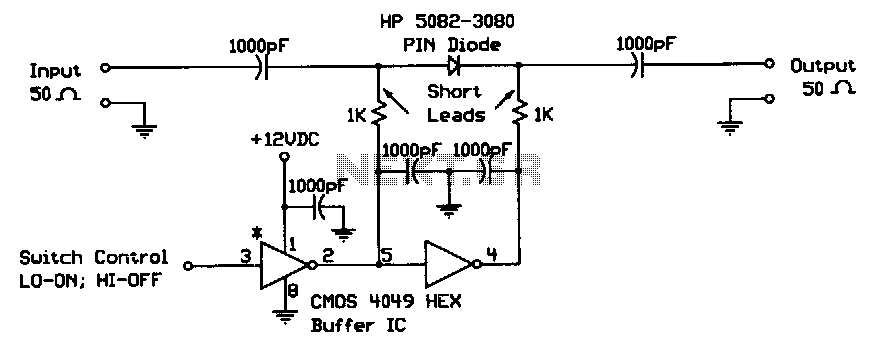
When the digital logic level at the control input is low, the PIN diode is forward-biased by the CMOS gates. The two 1-KΩ bias resistors limit this current to the PIN diode's safe forward current limit. In this state,...
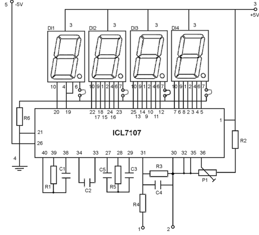
This is an easy-to-build yet highly accurate digital voltmeter designed as a panel meter. It can be utilized in DC power supplies or any application requiring precise voltage readings. The circuit uses the CL7107 Analog to Digital Converter (ADC)...
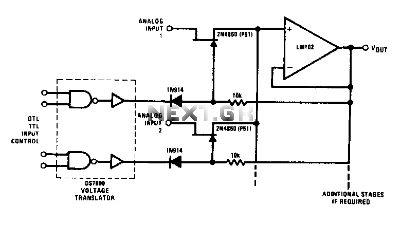
This analog switch utilizes the 2N4860 JFET, which features a low on-resistance of 25 ohms and minimal leakage current. The LM102 is employed as a voltage buffer in the circuit. Additionally, this configuration can be modified for use in...
Warning: include(partials/cookie-banner.php): Failed to open stream: Permission denied in /var/www/html/nextgr/view-circuit.php on line 713
Warning: include(): Failed opening 'partials/cookie-banner.php' for inclusion (include_path='.:/usr/share/php') in /var/www/html/nextgr/view-circuit.php on line 713