
Timer switch circuit

Part List
R1=1 Mohms C4=100nF 63V IC2=LM555
R2=330 Kohms C1-2=100uF 16V RV1=470 Kohms pot.
R3=680 ohms C3=1000uF 16V RL1-2=12V >120 ohms Relay
R4=2.2 Kohms D1=1N4148 S1-2=Push button n.o
R5-7=4.7 Kohms D2-3-4=1N4001 S3=2X2 switch
R6=47 Kohms Q1=BC214
R8-9=22 Kohms IC1=LM741
The described circuit operates as a delay timer for a relay, utilizing the LM555 timer integrated circuit (IC2) to control the timing mechanism. The circuit is powered by a +12V supply, which energizes the relay (RL1) after a predetermined delay of 100 seconds.
The configuration of the LM555 timer is set in monostable mode, where it generates a single output pulse in response to a trigger input. The timing period is determined by the resistor-capacitor (RC) network formed by R1, R2, and C1-2. When the circuit is powered, the capacitor charges through R1 and R2, and once it reaches approximately 2/3 of the supply voltage, the output of the LM555 transitions to a high state, energizing the relay.
The circuit also includes a variable resistor (RV1) that allows adjustment of the timing range, providing flexibility in the delay period. The additional components, such as the diodes (D1, D2, D3, D4), serve to protect the circuit from back EMF generated by the relay coil when it is de-energized.
The push button switch (S1-2) is utilized to manually trigger the timer, while the two-position switch (S3) allows selection between different timing ranges, specifically between 6-60 seconds and 1-10 minutes for automatic turn-off functionality.
Resistors R3 to R9, along with Q1 (a BC214 transistor), are used for signal amplification and conditioning within the circuit, ensuring reliable operation of the timer and relay. The use of capacitors C3 and C4 aids in stabilizing the power supply and filtering noise, which is critical for the proper functioning of the LM555 timer and overall circuit performance.
This design provides a robust solution for applications requiring delayed relay activation, with adjustable timing options to suit various operational needs.A 100 second delayed turn ON relay RL1 switch, if plug power +12V in circuit. In Fig.2 see a two range 6-60 second and 1-10 minute auto turn off relay timer circuit, with 555. Part List R1=1 Mohms C4=100nF 63V IC2=LM555 R2=330 Kohms C1-2=100uF 16V RV1=470 Kohms pot. R3=680 ohms C3=1000uF 16V RL1-2=12V >120 ohms Relay R4=2.2 Kohms D1=1N4148 S1-2=Push button n.o R5-7=4.7 Kohms D2-3-4=1N4001 S3=2X2 switch R6=47 Kohms Q1=BC214 R8-9=22 Kohms IC1=LM741 🔗 External reference
Related Circuits
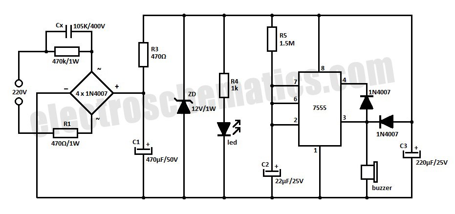
This is a simple power resumption alarm circuit that can be installed within the switch box. It emits beeping sounds when power is restored following a power failure. The power resumption alarm circuit is designed to provide an audible alert...
The purpose of this circuit is to animate shop windows using a capacitive sensor positioned behind a postcard-like banner. The card is placed against the glass inside the shop window, allowing visitors to activate the relay by placing their...
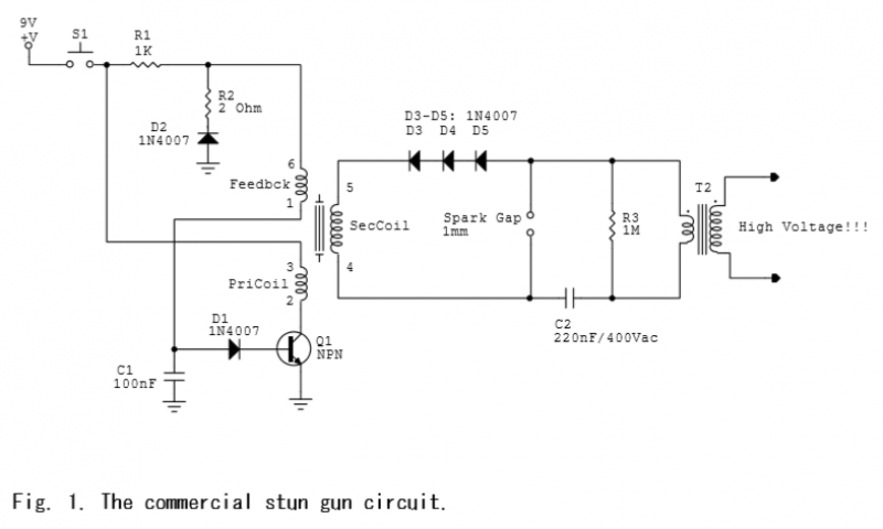
A commercial stun gun circuit that generates approximately 100 kV pulses from a 9V battery is illustrated in Figures 1-2. The core of the circuit is a power oscillator centered around transistor Q1. When switch S1 is activated, capacitor...
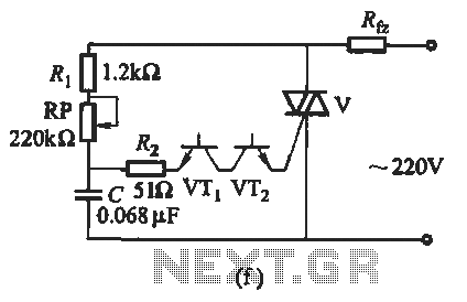
The introduction for a unidirectional thyristor trigger circuit is also applicable to the TRIAC. Various configurations are presented in Figure 16-28. Figures 16-28 (a) and (b) illustrate a direct trigger circuit; Figure 16-28 (c) depicts a dual diode trigger...
This circuit generates the power required to operate a bipolar stepper motor. It allows for adjustments in both the rotation speed and direction of the motor. The design includes two integrator circuits (A1, A3) and an amplifier (A2) connected...
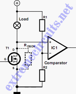
In applications where a MOSFET is used to switch a load, it is relatively straightforward to incorporate short-circuit or overload protection. This can be achieved by utilizing the internal resistance RDS(ON), which generates a voltage drop proportional to the...