
Digital Timer Light Switch
The described circuit functions as a digital timer switch, commonly employed in various lighting applications to automate the on/off states of lights. The core of the circuit typically integrates a microcontroller, such as a PIC (Peripheral Interface Controller) or a custom-designed integrated circuit (IC), which serves as the timing mechanism and control unit.
The circuit is designed to interface with the alternating current (AC) supply, allowing the timer to synchronize its internal clock with the AC line frequency, typically 50 or 60 Hz. This synchronization is crucial as it enables the timer to accurately determine the timing of the trigger pulses. The AC signal is often fed into an optoisolator or zero-crossing detector, which isolates the microcontroller from the high voltage AC line while providing a clean digital signal that represents the AC line's zero-crossing points.
Upon detecting the zero-crossing, the microcontroller can generate precise timing intervals for activating or deactivating the connected load, such as a light bulb. The timing can be programmed or set through user inputs, which may include buttons or a touchscreen interface, depending on the sophistication of the timer module.
Additional components in the circuit may include power supply filtering capacitors, resistors for current limiting, and protection diodes to safeguard against voltage spikes. The output stage typically consists of a relay or a solid-state switch (like a TRIAC) that controls the power delivered to the load, ensuring that the circuit can handle the required voltage and current levels.
Overall, this digital timer circuit showcases a practical application of microcontroller technology in enhancing the functionality and convenience of traditional light switches, allowing for programmable lighting solutions that can improve energy efficiency and user experience.Typical circuit representative of those used in most light switch type digital timers. The timer module is normally a PIC or custom chip, and it syncs to the AC line so that a trigger pulse can be supplied at the right moment. 🔗 External reference
Related Circuits
To eliminate circulating current in a zero-voltage switch three-level DC converter during its zero state, a zero-voltage zero-current switch three-level DC converter circuit has been proposed. The primary distinction between this circuit and the standard zero-voltage switch three-level DC...
Dodge Durango Fog Light Wiring Diagram. The Dodge Durango fog light wiring diagram provides a visual representation of the electrical connections and components involved in the fog light system of the vehicle. This diagram typically includes the battery, fog light...
If the ground of the Arduino is disconnected from the negative terminal of the power supply, current flows through the MOSFET, even when the switch is not closed. In an electronic circuit involving an Arduino and a MOSFET, maintaining a...
A switching power supply with an output voltage significantly lower than its input voltage exhibits an interesting characteristic: the current drawn by the supply is less than its output current. However, the input power (UI) is greater than the...
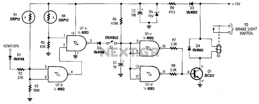
This circuit activates the brake lights of a parked car when headlights from an approaching vehicle are detected, alerting the driver of the oncoming vehicle about the stationary car. LDR4 serves as the sensor, while LDR1 deactivates the circuit...
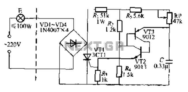
The circuit is a one-way ordinary transistor-triggered dimmer light circuit. It uses a complementary amplifier configuration with transistors VT2 and VT3 to form the thyristor trigger circuit for VT1. The circuit operates with a 220V alternating current through the...
Warning: include(partials/cookie-banner.php): Failed to open stream: Permission denied in /var/www/html/nextgr/view-circuit.php on line 713
Warning: include(): Failed opening 'partials/cookie-banner.php' for inclusion (include_path='.:/usr/share/php') in /var/www/html/nextgr/view-circuit.php on line 713