
digital to analog converters

The circuit operates by converting binary input signals into a corresponding analog voltage level. Each switch (b0 to b3) represents a binary digit, where the state of each switch determines whether it contributes to the output voltage. When a switch is in the ON position, it connects to the logic HIGH voltage level, contributing a weighted current based on its binary significance. The feedback resistor (Rf) plays a critical role in scaling the output voltage; its value must be chosen to ensure that the output remains within the operational limits of the op-amp.
In the binary-weighted resistor configuration, each resistor is typically chosen to be half the value of the previous one, allowing for precise control over the current contributions from each switch. As the number of inputs increases, the complexity of using binary-weighted resistors grows, leading to potential inaccuracies due to resistor tolerances. The R and 2R method simplifies this by using only two resistor values, which reduces the number of components needed and enhances reliability.
The output waveform produced by the D/A converter is a staircase function, which is a common characteristic of such converters. Each step represents a discrete voltage level corresponding to a unique binary input combination. The accuracy of the output can be affected by several factors, including the quality of the resistors used, the stability of the power supply, and the op-amp's characteristics. To ensure optimal performance, careful consideration must be given to the component selection and circuit layout.A D/A converter using binary-weighted resistors is shown in the figure below. In the circuit, the op-amp is connected in the inverting mode. The op-amp can also be connected in the non-inverting mode. The circuit diagram represents a 4-digit converter. Thus, the number of binary inputs is four. We know that, a 4-bit converter will have 24 = 16 com binations of output. Thus, a corresponding 16 outputs of analog will also be present for the binary inputs. Thus, according to the position (ON/OFF) of the switches (bo-b3), the corresponding binary-weighted currents will be obtained in the input resistor. The current through Rf will be the sum of these currents. This overall current is then converted to its proportional output voltage. Naturally, the output will be maximum if the switches (b0-b3) are closed The output is a negative going staircase waveform with 15 steps of -).
5V each. In practice, due to the variations in the logic HIGH voltage levels, all the steps will not have the same size. The value of the feedback resistor Rf changes the size of the steps. Thus, a desired size for a step can be obtained by connecting the appropriate feedback resistor. The only condition to look out for is that the maximum output voltage should not exceed the saturation levels of the op-amp.
Metal-film resistors are more preferred for obtaining accurate outputs. If the number of inputs (>4) or combinations (>16) is more, the binary-weighted resistors may not be readily available. This is why; R and 2R method is more preferred as it requires only two sets of precision resistance values.
A D/A converter with R and 2R resistors is shown in the figure below. As in the binary-weighted resistors method, the binary inputs are simulated by the switches (b0-b3), and the output is proportional to the binary inputs. Binary inputs can be either in the HIGH (+5V) or LOW (0V) state. Let b3 be the most significant bit and thus is connected to the +5V and all the other switchs are connected to the ground.
🔗 External reference
Related Circuits
Due to their speed, accuracy, effectiveness, and cost-efficiency, infrared (IR) digital thermometers have supplanted traditional mercury thermometers. An ear digital thermometer utilizes a thermopile sensor to measure the infrared heat emitted by the eardrum, which correlates with the temperature...
The operation of the converter is based on the weighted addition and transfer of the analog input levels to the digital output levels. It consists of... The converter functions by utilizing a weighted summation technique to process analog signals and...
This electronic clock comprises the LM8365 and the LDD640R displays. The LM8365 can show the hour/minute and month/day. Users can set two alarm outputs, AD1 and AD2, by pressing either the 12h or 24h button. The operating voltage range...
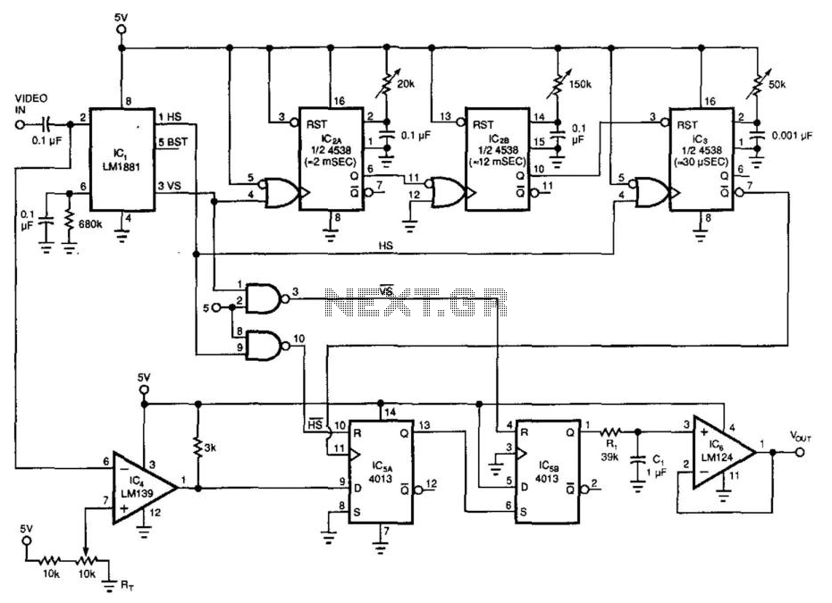
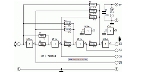
By utilizing a low-cost RS-170 camera and this circuit, a voltage that indicates the position of an object within the camera's field of view is generated. IC2A and IC2B create a valid video gate that keeps IC3 in a...
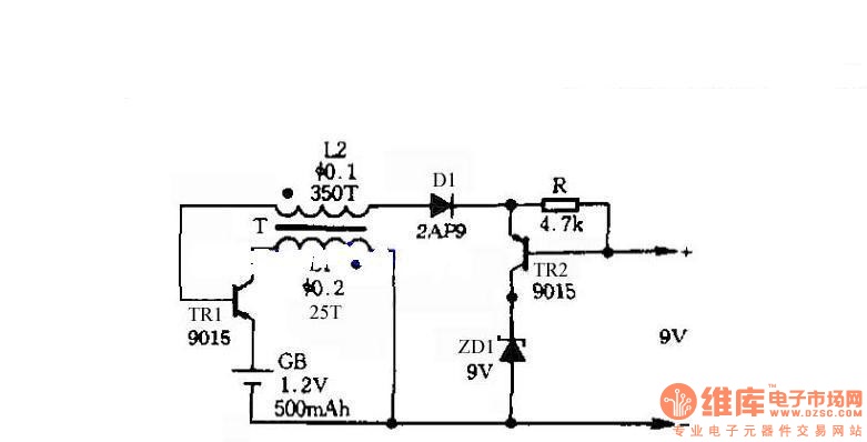
The circuit does not require a separate power switch or transformation to control the switches on the table. It offers advantages such as low power consumption, stability, reliability, and no impact on instrument accuracy. The transformer T in the...
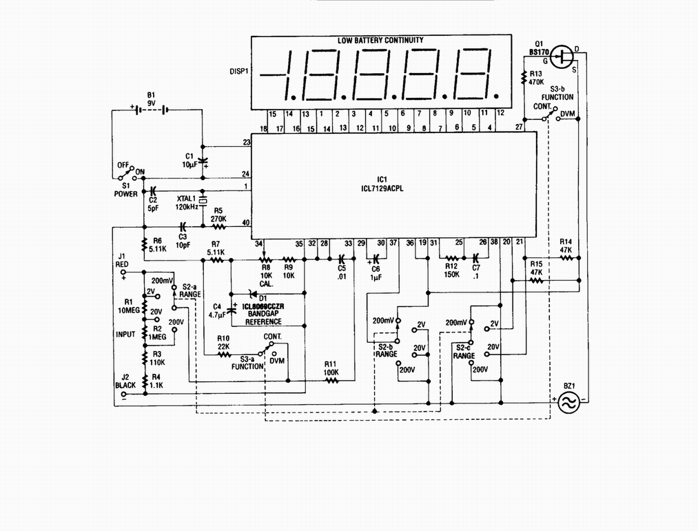
Single-chip digital voltmeter. This 4 1/2-digit DVM circuit is built around a Maxim ICL7129ACPL A/D converter and LCD driver. An ICL8069 CCZR 1.2-V band-gap reference diode is used for accuracy. The described circuit is a single-chip digital voltmeter (DVM) utilizing...