
Single-chip digital voltmeter
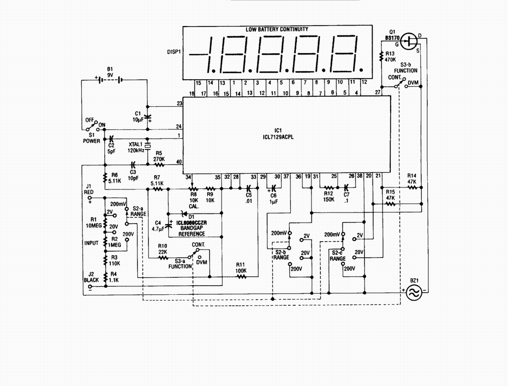
The described circuit is a single-chip digital voltmeter (DVM) utilizing the Maxim ICL7129ACPL integrated circuit, which serves as both the analog-to-digital (A/D) converter and the liquid crystal display (LCD) driver. The 4 1/2-digit resolution indicates that the DVM can display values from 0.000 to 19.999 volts with a high degree of precision. The ICL7129ACPL incorporates features such as auto-zeroing and low drift, which enhance measurement accuracy and reliability.
To ensure stable and accurate voltage references, the circuit employs the ICL8069 CCZR, a 1.2-V band-gap reference diode. This component provides a stable reference voltage for the A/D converter, which is crucial for achieving precise voltage measurements. The band-gap reference is designed to maintain its output voltage over a wide range of temperatures and supply voltages, thereby improving the overall performance of the DVM.
The circuit typically includes additional components such as resistors and capacitors for signal conditioning, filtering, and noise reduction. The input stage may consist of a voltage divider to scale the input voltage to the appropriate range for the A/D converter. Furthermore, the LCD driver functionality integrated into the ICL7129ACPL allows for direct control of the display, simplifying the design and reducing the number of external components required.
In summary, this digital voltmeter circuit combines advanced IC technology with precision reference components to deliver accurate and reliable voltage measurements in a compact design, making it suitable for a variety of applications in electronics testing and measurement.Single-chip digital voltmeter. This 4 1/2-digit DVM circuit is built around a Maxim ICL7129ACPL A/D converter and LCD driver. An ICL8069 CCZR 1.2-V band-gap reference diode is used for a. 🔗 External reference
Related Circuits
This circuit allows for amplifier volume control without the need for a potentiometer, utilizing an IC DS1669. The operating voltage for this type of IC ranges from 4.5 volts to 8 volts; however, in this circuit, it is used...

This design outlines a high impedance DC voltmeter circuit utilizing the uA741 integrated circuit (IC). The uA741 is configured as a non-inverting DC amplifier. The circuit incorporates negative feedback through a DC meter that requires 1 mA for full-scale...
This circuit provides a digital square wave that can be viewed directly or used to drive other circuits. It used the CMOS 4047 Low-Power Monostable/Astable Multivibrator. As used in Tom Duncan's Adventures with Digital Electronics Book, to drive CMOS...
Measurement of physiological parameters such as heart rate and respiration rate is essential in the medical field. A simple method for measuring respiration rate utilizes a displacement transducer, which is fast and cost-effective. This method allows for the measurement...

The circuit consists of the MAX1494 digital strain gauge, as illustrated in Figure 5-31. It includes a bridge formed by resistance strain gauges and a temperature compensation sheet. The standard quasi-resistance values Rl and R are incorporated into the...
This clock timer uses a PIC16F628 microcontroller to display 3 and 1/2 digit time and control an external load. The clock includes a calendar with leap year and optional daylight savings adjustments. The timer output can be set from...