
Dimmer Switch General Purpose Electric Power Control
Dimmer switches operate by varying the voltage supplied to the load, effectively controlling the brightness of the connected lighting or the speed of electric motors. Typically, they utilize a semiconductor device, such as a triac, to chop the AC waveform, thereby reducing the average power delivered to the load.
In a basic dimmer switch circuit, the main components include the triac, a variable resistor (potentiometer), and an optoisolator for safety. The potentiometer allows the user to adjust the resistance, which in turn changes the firing angle of the triac. This firing angle is critical as it determines how much of the AC waveform is allowed to pass through to the load, directly influencing the brightness of the lamp or the speed of the motor.
The circuit may also incorporate a snubber circuit, which consists of a resistor and capacitor in series, to protect the triac from voltage spikes and to improve performance with inductive loads like motors. Additionally, dimmer switches can be designed to include features such as remote control capabilities, programmable settings, and compatibility with various lighting technologies, including incandescent, LED, and fluorescent lamps.
When designing or implementing a dimmer switch circuit, it is essential to consider the load type and compatibility, as not all dimmers are suitable for every type of light source. Proper thermal management is also crucial, as dimmers can generate heat during operation, necessitating heat sinks or other cooling methods to ensure reliability and longevity of the device.Dimmer Switch Introduction Dimmer switch can be used to replace your electrical switch for lamps, heaters, or some types of electric motor. Dimmer switches.. 🔗 External reference
Related Circuits
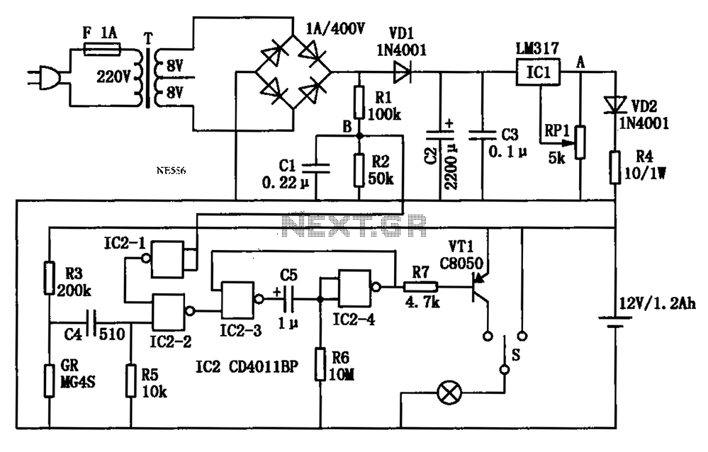
An automatic multipurpose emergency lights circuit is presented. Typically, emergency lights are connected to the mains for standby when fully charged. In the event of a sudden power failure, the ambient light transitions from strong to weak, indicating a...
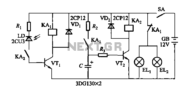
When driving at night and approaching another vehicle, traffic regulations dictate that the distance between the two vehicles should be maintained. This is achieved by alternately activating and deactivating the high beams, while utilizing either the wide lights or...
The equation is as follows: If a circuit has a resistance of 25 ohms and a potential of 125 volts, the current drawn in this circuit would be 5 amps. This basic circuit provides a foundational understanding for the...
Figure 15-22 illustrates a doorbell system that consists of a monostable timing circuit, a password switch, a NAND gate circuit, and a sound output circuit. The operation of the circuit is designed such that when the password switch is...
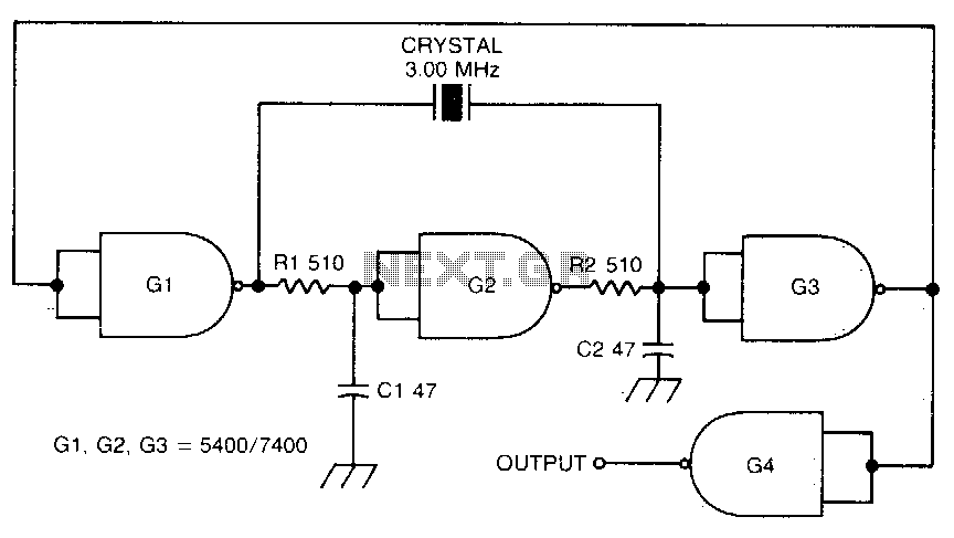
This circuit oscillates without the crystal. When the crystal is included in the circuit, the frequency will match that of the crystal. The circuit exhibits good starting characteristics even with low-quality crystals. This circuit design features a basic oscillator configuration...
This circuit can be utilized as a replacement for the single current-limiting resistor typically found in inexpensive battery chargers. The alternative presented here will prove beneficial over time, as it eliminates the need to discard NiCd batteries after a...
Warning: include(partials/cookie-banner.php): Failed to open stream: Permission denied in /var/www/html/nextgr/view-circuit.php on line 713
Warning: include(): Failed opening 'partials/cookie-banner.php' for inclusion (include_path='.:/usr/share/php') in /var/www/html/nextgr/view-circuit.php on line 713