
Switchless NiCd-NiMH Battery Charger
This circuit serves as an effective solution for charging NiCd batteries with improved longevity and efficiency. The use of the LM317 voltage regulator in a constant current configuration allows for precise control of the charging current without the need for additional resistors or switches. The incorporation of a voltage dropper (D1) and a biasing transistor (T1) enables automatic activation of the constant current mode when a battery is connected, ensuring that the charging process begins immediately.
The design accounts for safe operation by including a diode (D4) to prevent reverse current flow, which could potentially damage the battery or the charger itself. The calculation for the charging current based on resistor values ensures that the batteries are charged at an appropriate rate, promoting longevity and efficiency.
Furthermore, the thermal considerations for the LM317 are addressed by recommending a heat sink, which is crucial for maintaining the performance of the regulator under load. The recommendation to use a mains adapter with a DC output emphasizes the importance of electrical safety in the design, reducing the risk associated with direct mains voltage exposure.
Overall, this circuit is a robust solution for charging different types of rechargeable batteries while addressing common issues associated with conventional chargers, such as inadequate current regulation and safety concerns.This circuit may be used to replace the single current limiting resistor often found in dirt cheap battery chargers. The alternative shown here will eventually pay off because you no longer have to throw away your NiCds after three months or so of maltreatment in the original charger.
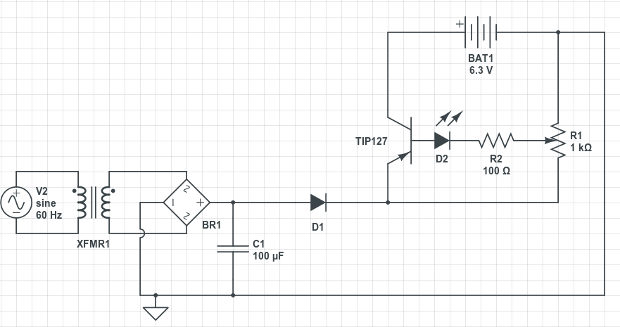
The circuit diagram shows an LM317 in constant-current configur ation but without the usual fixed or variable resistor at the ADJ pin to determine the amount of output current. Also, there is no switch with an array of different resistors to select the charge currents for three cell or battery types we wish to charge: AAA, AA and PP3 (6F22).
When, for example, an empty AAA cell is connected, the voltage developed across R1 causes T1 to be biased via voltage dropper D1. This results in about 50 µA flowing from the LM317`s ADJ pin into the cell, activating the circuit into constant-current mode.
D4 is included to prevent the battery being discharged when the charger is switched off or without a supply voltage. The charging current I is determined by R1/R3/R3 as in R(n) = (1. 25 + Vsat) / I where Vsat is 0. 1 V. The current should be one tenth of the nominal battery capacity ” for example, 170 mA for a 1700-mAh NiCd AA cell.
It should be noted that PP3` rechargeable batteries usually contain seven NiCd cells so their nominal voltage is 8. 4 V and not 9V as is often thought. If relatively high currents are needed, the power dissipation in R1/R2/R3 becomes an issue. As a rule of thumb, the input voltage required by the charger should be greater than three times the cell or battery (pack) voltage.
This is necessary to cover the LM317`s dropout voltage and the voltage across R(n). Two final notes: the LM317 should be fitted with a small heat sink. With electrical safety in mind the use of a general-purpose mains adapter with DC output is preferred over a dedicated mains transformer/rectifier combination. 🔗 External reference
Related Circuits
Most off-the-shelf car battery chargers cannot be left connected to the battery for long periods of time as overcharging can cause battery damage. The operation of car battery chargers typically involves converting alternating current (AC) from a wall outlet into...
Most 24V power systems in trucks, 4WDs, RVs, boats, and similar applications utilize two series-connected 12V lead-acid batteries. The charging system is designed to maintain the total voltage of the two batteries. If one battery begins to fail, the...
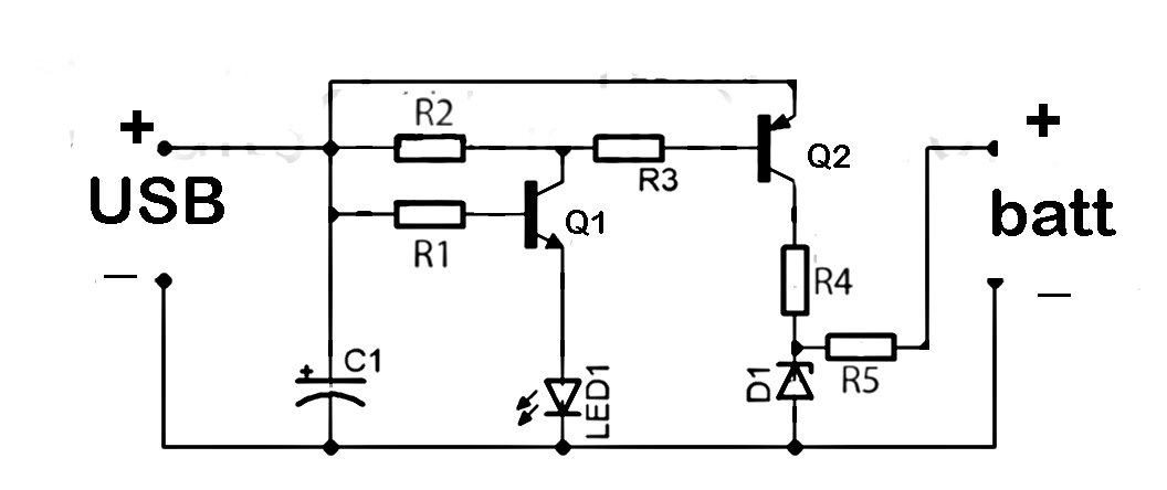
This document discusses the series used in USB connections for charging batteries. The output voltage ranges from 4.7 volts to 5 volts DC, which is suitable for charging mobile phones and other battery types. The circuit described enhances the...
A small electronic switch connects a battery to equipment for a specific duration when a push-button is momentarily pressed. The circuit also considers ambient light levels; when it is dark, the display cannot be read, so it is logical...
The circuit serves an educational purpose, necessitating simplicity. The construction will utilize only components that are already available, including a variety of resistors, capacitors, transistors, and no integrated circuits (ICs). The circuit is designed to demonstrate fundamental electronic principles through...
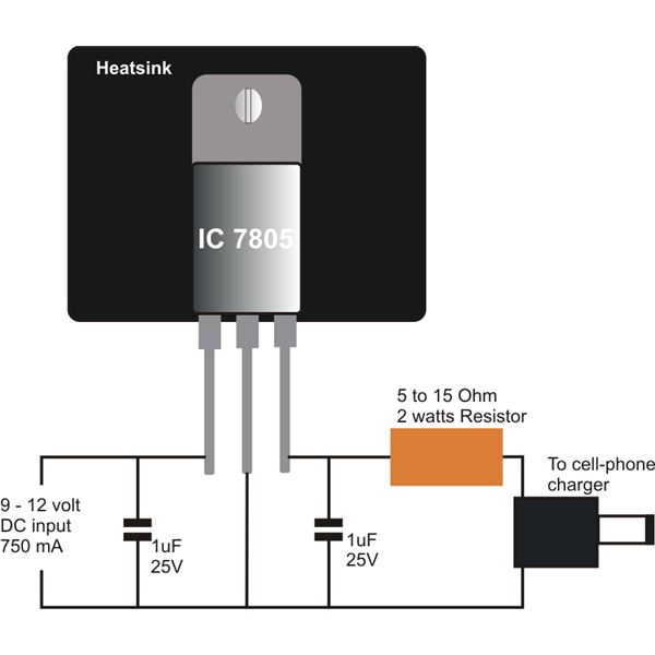
Construct a straightforward DC to DC mobile battery charger to charge your mobile phone battery at any time and location by connecting it to a 12-volt source from a car or motorbike battery. This mobile battery charger circuit is designed...