
Direct coupling audio power amplifier configuration A741 circuit
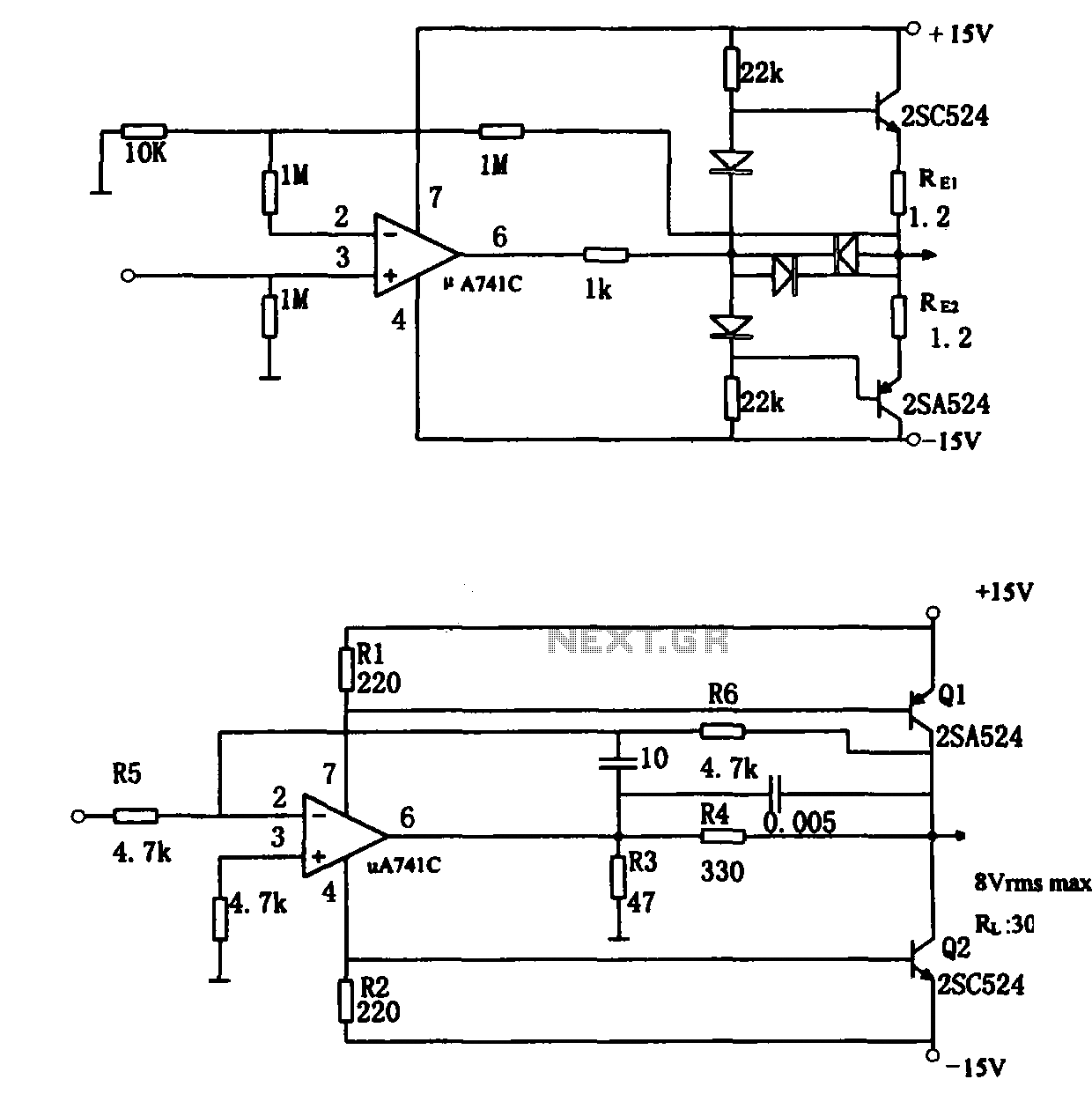
The direct coupling audio power amplifier circuit can be divided into two distinct configurations, each catering to specific performance requirements. The first configuration (a) employs a straightforward design that integrates an operational amplifier with a complementary symmetry emitter follower. This design is characterized by its simplicity and ease of implementation, making it suitable for a variety of applications. However, it is important to note that this configuration yields lower power utilization due to inherent limitations in the design.
In this configuration, two transistors are arranged in series with a pole resistance of 1.2 ohms, which plays a crucial role in safeguarding the amplifier transistor at the output terminal of the operational amplifier. The external 1k ohm resistor connected to pin 6 of the A741 operational amplifier further enhances overcurrent protection, ensuring the reliability of the circuit during operation. The voltage amplification factor of approximately 101.4 indicates the circuit's capability to amplify audio signals effectively. The choice of diodes (1S953) and amplifier tubes (2SC524 and 2SA524) is critical, as these components determine the overall performance and efficiency of the amplifier.
The second configuration (b) shifts the focus to a more efficient design by utilizing the operational amplifier to supply current excitation to a complementary symmetry common emitter amplifier. This approach allows for a power output of around 2W, which is suitable for driving various audio loads. The A741C operational amplifier, known for its compact size, operates in conjunction with two class AB amplifier tubes that function in an enlarged state, optimizing power consumption while maintaining high efficiency. The output current, typically in the range of a few milliamps, aligns closely with the supply current, ensuring that the circuit operates efficiently under varying load conditions.
In this configuration, the positive and negative power terminals of the operational amplifier are strategically connected to the bases of transistors Q1 and Q2, facilitating the necessary base excitation current for optimal performance. Resistor R3, valued at 47 ohms, is instrumental in augmenting the power supply current, thereby increasing the base excitation current for the power amplifier tubes. Additionally, resistor R4 serves as a vital current limiting component, providing overcurrent protection for the A741C operational amplifier, thereby enhancing the circuit's reliability and longevity. Overall, these configurations exemplify effective design strategies in audio power amplification, balancing simplicity, efficiency, and performance.As shown for the direct coupling audio power amplifier. When using an integrated operational amplifier constituting the audio power amplifier, there are usually two practical forms.The first practical form as shown in (a), the structure of the circuit is in the output of op amp plus complementary symmetry emitter follower, this form of structure is simple, easy to use, but lower power utilization. Figure (a) know, shoot the circuit two transistors are connected in series pole resistance RE (1.2 ), whose role is to implement over-current amplifier transistor in the integrated operational amplifier output terminal (pin 6) External 1k resistor to A741 also play the role of overcurrent protection.
Figure (a) in which the voltage amplification factor of about 101,4 diodes are 1S953, amplifier tube for the tube, model 2SC524 and 2SA524.The second practical form as shown in (b), the circuit is the use of the operational amplifier supply current excitation complementary symmetry common emitter amplifier, power output parameters as shown in the figure is about 2W. A741C power operational amplifier itself is small, the output stage of the two class AB amplifier tube operating in the enlarged state, the power consumption is also small, and thus a higher efficiency when taking a few milliamps of output current, supply current is substantially close to the load current.
Positive and negative power terminal of the operational amplifier (pin 7,4), respectively, with the base of transistor Q1 and Q2 is connected to that supply current to become operational amplifier Q1 and Q2 base excitation current. Role Figure (b) of the resistor R3 (47 ) is to increase the power supply current, which increases both the power amplifier tube base excitation current.
Resistor current limiting resistor R4, to A741C play the role of overcurrent protection.
Related Circuits
Integrated circuits (ICs) are commonly utilized in various audio amplifiers, particularly in compact circuits. While transistors are convenient alternatives, they offer several advantages, such as the ability to repurpose old equipment to create smaller circuits, which may be harder...
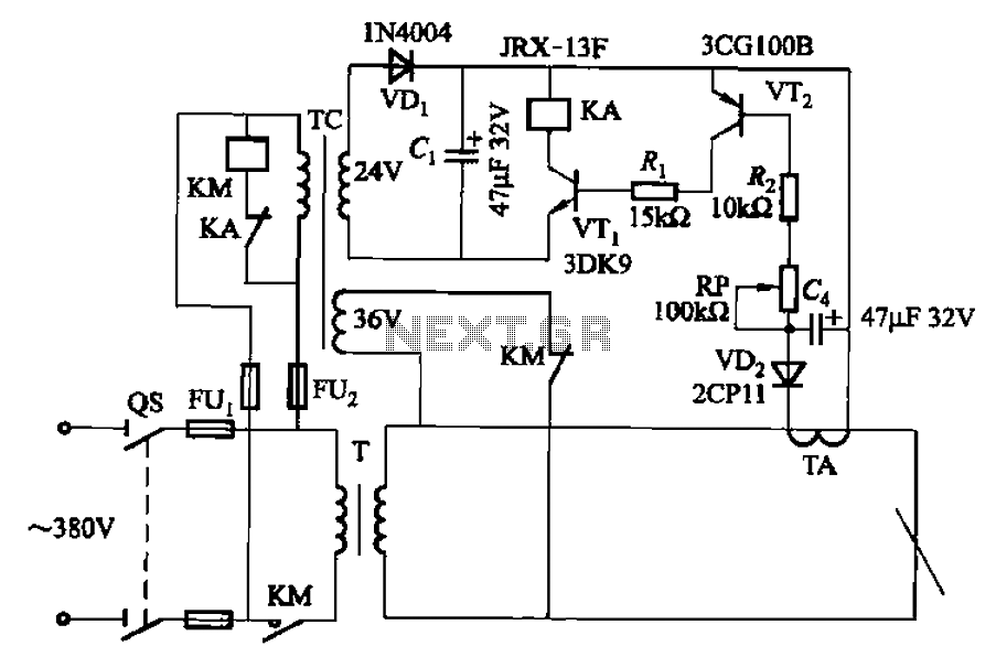
The AC arc welding machine's transistor load path for the power from the second circuit is illustrated. The figure shows a current transformer with a core cross-section of 25 mm². The transformer has a primary winding with a certain...
Construct a low-cost and relatively simple robot that activates whenever a desk lamp is illuminated. The design does not incorporate any sensors. This robot can be designed using basic electronic components to create a simple activation mechanism based on light...
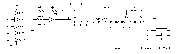
Generating long delays of several hours can be achieved using a low-frequency oscillator and a binary counter. A single Schmitt Trigger inverter stage (1/6 of 74HC14) functions as a square wave oscillator, producing a low frequency of approximately 0.5...
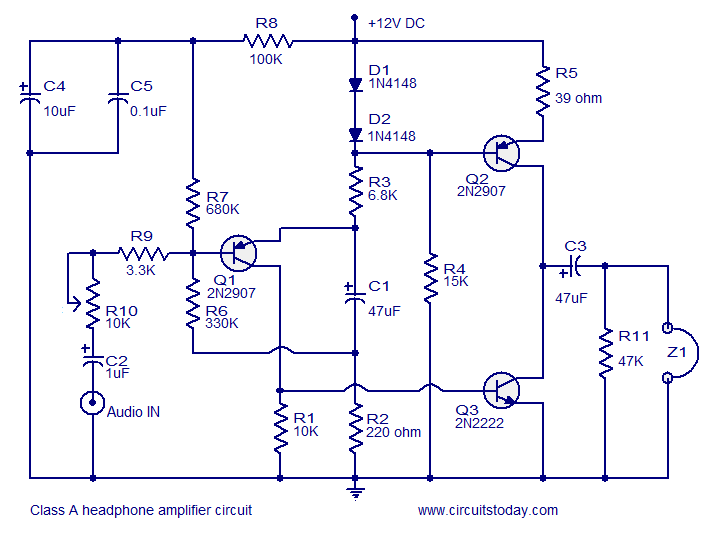
Transistor amplifier circuits that are simple and easy to construct. This includes a headphone amplifier, a four-transistor amplifier, and a low-power amplifier. Transistor amplifier circuits are fundamental components in electronic design, offering various applications ranging from audio amplification to signal...
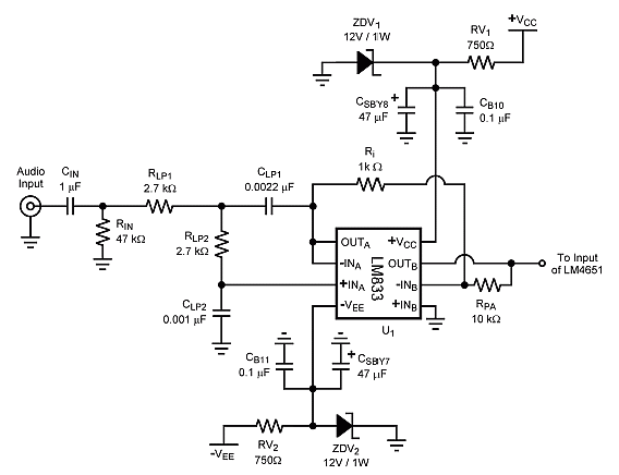
The combination of the LM4651 driver IC and the LM4652 power MOSFET Class D power amplifier IC provides a high-efficiency amplifier solution, suitable for self-powered speakers, subwoofers, and quality car boosters. The LM4651 is a fully integrated conventional pulse...
Warning: include(partials/cookie-banner.php): Failed to open stream: Permission denied in /var/www/html/nextgr/view-circuit.php on line 713
Warning: include(): Failed opening 'partials/cookie-banner.php' for inclusion (include_path='.:/usr/share/php') in /var/www/html/nextgr/view-circuit.php on line 713