
CD4040 Generating Long Time Delays Circuit
The circuit utilizes a low-frequency oscillator combined with a binary counter to facilitate extended timing delays. The Schmitt Trigger inverter provides a stable square wave output, which is critical for the operation of the binary counter. The output frequency of 0.5 Hertz translates to a period of two seconds, which is then divided down through the 12-stage CD4040 counter. Each flip-flop in the counter divides the input frequency by two, leading to a cumulative delay of approximately one hour by the time the final output stage is reached.
The inclusion of the 10K resistor serves a dual purpose: it protects the inverter's input from excessive discharge currents and enhances overall circuit reliability. This precaution is particularly important in applications where the circuit may be disconnected unexpectedly, as it helps prevent damage to sensitive components.
Adjustments to the timing can be made by altering the values of the resistor and capacitor used in the oscillator stage. For instance, increasing the capacitance or resistance will result in a lower frequency output, thereby extending the delay time. Conversely, decreasing these values will shorten the timing duration. The flexibility of the RC timing network allows for customization to suit specific application requirements.
The reset function, facilitated by connecting pin 11 to the positive supply, allows for easy reinitialization of the timing cycle. This feature is essential for applications that require repeated timing sequences. The accuracy of the timing mechanism, while not as precise as that of a crystal oscillator, remains adequate for many practical applications, with a typical deviation of 1% to 2%, contingent upon the stability characteristics of the timing components used. Overall, this circuit provides a reliable and adjustable solution for generating long delays in various electronic applications.Generating long delays of several hours can be accomplished by using a low frequency oscillator and a binary counter as shown below. A single Schmitt Trigger inverter stage (1/6 of 74HC14) is used as a squarewave oscillator to produce a low frequency of about 0.
5 Hertz. The 10K resistor in series with the input (pin 1) reduces the capacitor discha rge current through the inverter input internal protection diodes if the circuit is suddenly disconnected from the supply. This resistor may not be needed but is a good idea to use. The frequency is divided by two at each successive stage of the 12 stage binary counter (CD4040) which yields about 1 hour of time before the final stage (Q12) switches to a high state.
Longer or shorter times can be obtained by adjusting the oscillator frequency or using different RC values. Each successive stage changes state when the preceding stage switches to a low state (0 volts), thus the frequency at each stage is one half the frequency of the stage before.
Waveform diagrams are shown for the last 3 stages. To begin the delay cycle, the counter can be reset to zero by momentarily connecting the reset line (pin 11) to the positive supply. Timing accuracy will not be as good as with a crystal oscillator and may only be around 1 or 2% depending on the stability of the oscillator capacitor.
🔗 External reference
Related Circuits
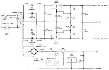
This bench power supply features three solid-state DC power supplies. The first supply provides an output of 1.5 to 15 volts at 1 ampere. The second supply offers a range of -1.5 to -15 volts at 1 ampere. The...
The Olimex P-40 development board will be utilized, though the circuit can also be constructed on a breadboard due to its simplicity. The schematic for the initial implementation of servo control is provided below. Servos, like any motors, can...
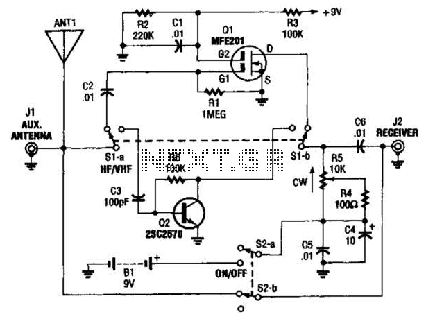
The AA-7 active antenna consists of two active components: Q1 (an MFE201 N-channel dual-gate FET) and Q2 (a 2SC2570 VHF silicon transistor), which form the foundation for two independent, switchable RF preamplifiers. The AA-7 active antenna is designed to enhance...
The K8000 DAC High Power Amplifier is an electronic amplifier with an adjustable output voltage ranging from 0 to 9 V and capable of delivering an output current of up to 9 Amperes. The K8000 DAC High Power Amplifier is...
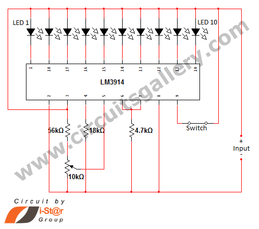
In various situations, it is necessary to indicate the amount of battery charge using methods such as LED dot displays or LED bar displays. This circuit utilizes the LM3914 integrated circuit to serve as a battery charge indicator with...
This circuit operates as a 9V DC power source supplying a 555 timer to generate a square wave. The output is then processed through a Half-Wave Series Multiplier (Villard Cascade) to achieve a high voltage DC output. The goal...